MULTIPLE
COLUMN
SELECTION
DEVICE
63
Alphabetic sorting can
be
accelerated considerably
by
the zero-elimination operation. Cards with long
names
or descriptions can
be
segregated from cards
with short names or descriptions.
In
the
example below,
card 1 may
be
sorted on all
12
colwnns, while card 2
requires sorting on only 5 columns.
Card Col. 1 2 3 4 5 6 7 8 9
10
11
12
Card 1
Card 2
CHRISTIANS
0 N
JONES
If
columns 6 through
12
are
wired
for
zero
elimina-
tion, all cards with names
as
short or shorter than
JONES will be rejected on the
first
sort and need not
be
sorted further until the regular sort on column 5
is
made.
The operator's knowledge of the data punched in
the sorting
field
will determine the best number of
columns to wire for
zero-eLimination
on the first sort,
as
well
as
whether or not smaller portions of the
field
should be wired for elimination on
successive
sorts.
The wiring and switch settings are the same
as
for
zero-elimination in numerical sorting.
Normal Sorting
With the zero-eliminate and the multiple column
selection switches turned off, all sorting selector
com-
mutator contact bars pushed out, and the single sort
brush replacing the multiple column brush,
sorting can
be
accomplished in the normal manner.
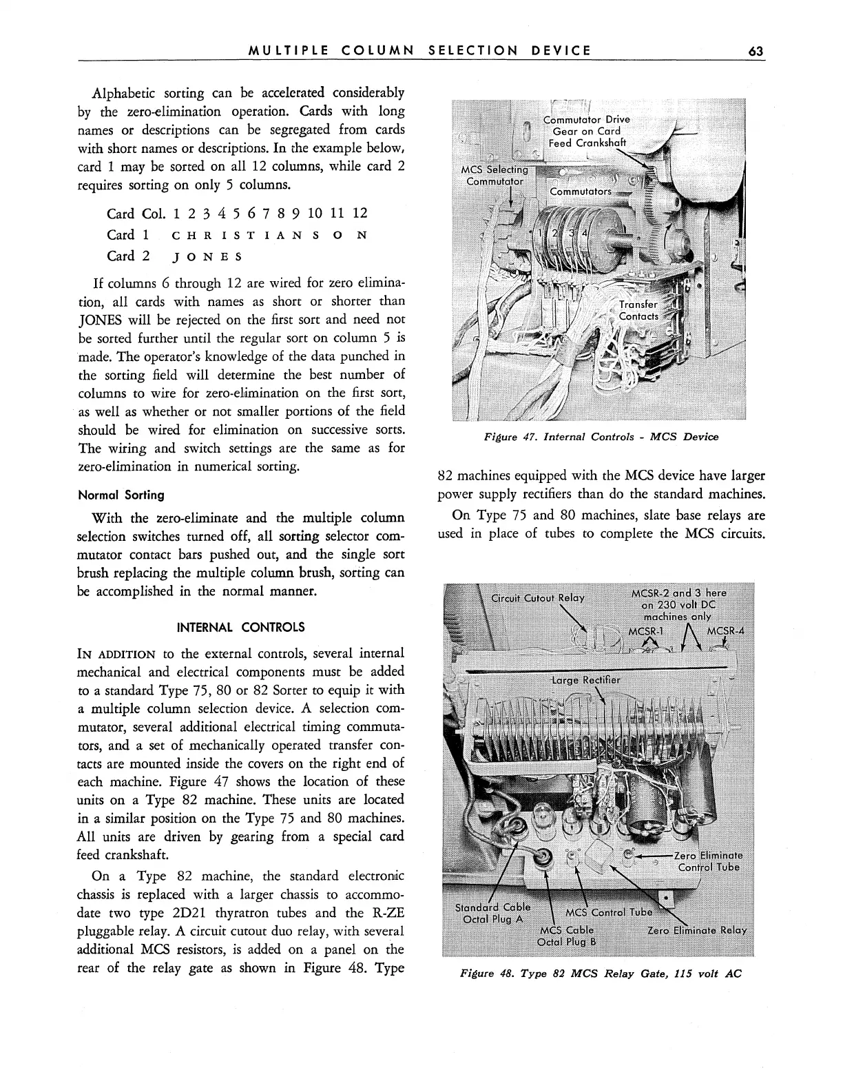
INTERNAL
CONTROLS
IN
ADDITION
to
the external controls, several internal
mechanical and electrical components must
be
added
to a standard Type 75,
80 or
82
Sorter to equip it with
a multiple column selection
device.
A selection
com-
mutator, several additional electrical timing commuta-
tors, and a set of mechanically operated transfer con-
tacts
are mounted inside the
covers
011 the right end of
each machine. Figure 47
shows
the location of these
units on a Type 82 machine. These units are located
in a similar position on the Type
75
and 80 machines.
All units are driven
by
gearing from a special card
feed
crankshaft.
On a Type
82
machine, the standard electronk
chassis
is
replaced with a larger
chassis
to accommo-
date two type 2D21 thyratron tubes and the R-ZE
pluggable relay. A circuit cutout
duo
relay, with several
additional
MCS
resistors,
is
added on a panel on the
rear of the relay gate
as
shown
in
Figure 48. Type
Figure 47. Internal Controls -
MCS
Device
82 machines equipped with the
MCS
device have larger
power supply rectifiers than
do
the standard machines.
On Type
75
and 80 machines, slate base relays are
used
in place of tubes to complete the
MCS
circuits.
Figure 48.
Type
82
MCS
Relay
Gate, 115
volt
AC