IBM
978
CARD
COUNTING
UNIT
FUNCTIONAL
PRINCIPLES
Introduction
The 978
is
used with, and under the control of, the
82 Sorter for the purpose of counting cards. The
counter unit performs a pocket distribution count for
all cards with or without card sorting. For normal
operation, a count
is
made of the cards entering each
pocket with a total of all cards accumulated in the
subtotal counter.
If
the cards have multiple punches,
the counters count each hole present in the card column.
The subtotal accumulates the total number of cards
and not the number of holes read.
Two switches control the operation of the counting
unit. The counter switch
is
positioned
ON
whenever
cards are counted.
When
this switch
is
positioned
ON,
the counting unit must be connected
to
the sorter. The
cable from the counting unit connects into an Elco
receptacle.
If
the cable
is
not connected
to
the Sorter
and the counter switch
is
positioned
ON,
the Sorter does
not operate. The count-only switch
is
positioned
ON
to suppress sorting while cards are counted. Digit sup-
pression
is
used to suppress sorting cards with specific
punches without suppressing the count of the respec-
tive punches.
The counting unit consists of 14 separate counters:
12 counters to count the punches in the card, one
counter to count rejected cards, and one counter to
accumulate a total of all cards. The counters are
mounted in two rows
across
the length of the counting
unit. The counters are numbered to correspond with
the particular hole counted. The counters in the top
row consist of
0 through 5 and reject. The counters in
the lower row consist of 6 through
12
and subtotal.
Each counter has a capacity of 99,999.
Reset
The counters are reset manually
by
turning the crank
at the right side of the counting unit.
It
is
necessary
to depress the detent lever located on the front of the
unit before the crank may
be
operated. The detent
lever serves
as
an interlock
to
prevent machine opera-
tion when the counters are not fully reset to zero.
When
the detent lever
is
depressed, it operates a switch
that opens the machine start circuit.
The reset crank resets the counters
by
turning a
shaft to which all the counters are geared.
At
the com-
76
pletion of the second crank revolution, a detent lever
engages in the counter reset shaft. This prevents further
movement of the reset mechanism until the detent
lever
is
again depressed.
Counters
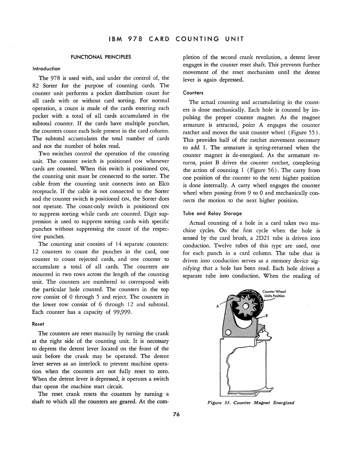
The actual counting and accumulating in the count-
ers
is
done mechanically. Each hole
is
counted
by
im-
pulsing the proper counter magnet. As the magnet
armature
is
attracted, point A engages the counter
ratchet and moves the unit counter wheel (Figure
55
) .
This provides half of the ratchet movement necessary
to add
1.
The armature
is
spring-returned when the
counter magnet
is
de-energized.
As
the armature re-
turns, point B drives the counter ratchet, completing
the action of counting 1 (Figure
56).
The carry from
one position of the counter to the next higher position
is
done internally. A carry wheel engages the counter
wheel when passing from 9 to
0 and mechanically con-
nects the motion to the next higher position.
Tube and Relay Storage
Actual counting of a hole in a card takes two ma-
chine
cycles.
On the first
cycle
when the hole
is
sensed
by
the card brush, a 2D21 tube
is
driven into
conduction. Twelve tubes of this type are used, one
for each punch in a card column. The tube that
is
driven into conduction serves
as
a memory device
sig-
nifying that a hole has been read. Each hole drives a
separate tube into conduction.
When
the reading of
Fi~ure
55.
Counter
Ma~net
Ener~ized