MULTIPLE
COLUMN
SELECTION
DEVICE
67
MCS
Selecting
Commutator
Zero eliminate
OFF
Switch
2·L
°ON
SOOKn
<1f------
t
"-
Control
Panel Wire
2000
/l.
o volts
- Constant current flow
+ through these two resistors.
t "
Voltage drop across this 1 meg.
resistor applied between cathode
and control grid of 2021 to give
approximately
2S volts negative
bias to the grid.
-40
volts
OFF
Zero eliminate
Q--e>D---Q
Switch
1.L
o
ON
Commutator 2
Standard
To
plus
potential
Bias
Osciflator
I
To
minus
potential
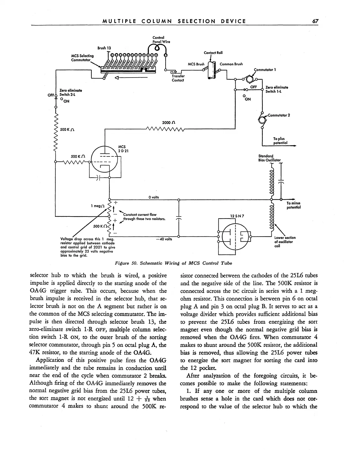
Figure
SO.
Schematic
Wiring
of
MCS
Control
Tube
selector hub to which the brush
is
wired, a positive
impulse
is
applied directly to the starting anode of the
OA4G trigger tube. This
occurs,
because when the
brush impulse
is
received in the selector hub, that
se-
lector brush
is
not on the A segment but rather
is
on
the common of the
MCS
selecting commutator. The
im-
pulse
is
then directed through selector brush 13, the
zero-eliminate switch 1-R
OFF,
multiple column
selec-
tion switch 1-R
ON,
to
the outer brush of the sorting
selector commutator, through pin 5 on octal plug
A,
the
47K resistor,
to
the starting anode of the OA4G.
Application of this positive pulse
fires
the OA4G
immediately and the tube remains in conduction until
near the end of the cycle when commutator 2 breaks.
Although firing of the OA4G immediately removes the
normal negative grid
bias
from the 25L6 power tubes,
the sort magnet
is
not energized until
12
+ i2 when
commutator 4 makes to shunt around the
500K
re-
sis
tor connected between the cathodes of the 25L6 tubes
and the negative
side
of the line. The 500K resistor
is
connected
across
the
DC
circuit in
series
with a 1 meg-
ohm resistor. This connection
is
between pin 6 on octal
plug A and pin 3 on octal plug
B.
It
serves
to
act
as
a
voltage divider which provides sufficient additional
bias
to prevent the 25L6 tubes from energizing the sort
magnet even though the normal negative grid bias
is
removed when the OA4G
fires.
When commutator 4
makes to shunt around the
500K resistor, the additional
bias
is
removed, thus allowing the 25L6 power tubes
to energize the sort magnet for sorting the card into
the
12
pocket.
After analyzation of the foregoing circuits,
it
be-
comes
possible to make the following statements:
1.
If
anyone
or more of the multiple column
brushes
sense
a hole in the card which does not cor-
respond to the value of the selector hub
to
which the