Power Supply
001
– Check all drive and power supply connections for proper installation.
– Power off the system unit.
– Check the power cord for continuity. Replace if necessary.
– Check for the correct line voltage from the power outlet, and verify that the
voltage selector switch (if present) is set for the correct voltage.
– Power on the system unit.
DOES THE POWER SUPPLY FAN RUN?
Yes No
002
– Go to Step 004.
003
– Go to Step 009 on page 2-28.
004
(From step 002)
– Disconnect the power cord from the back of the system unit.
Note: The J29 and J30 power and switch connectors are latched. To
remove a latched connector, press in the latch using the tip of a
screwdriver to release the connector.
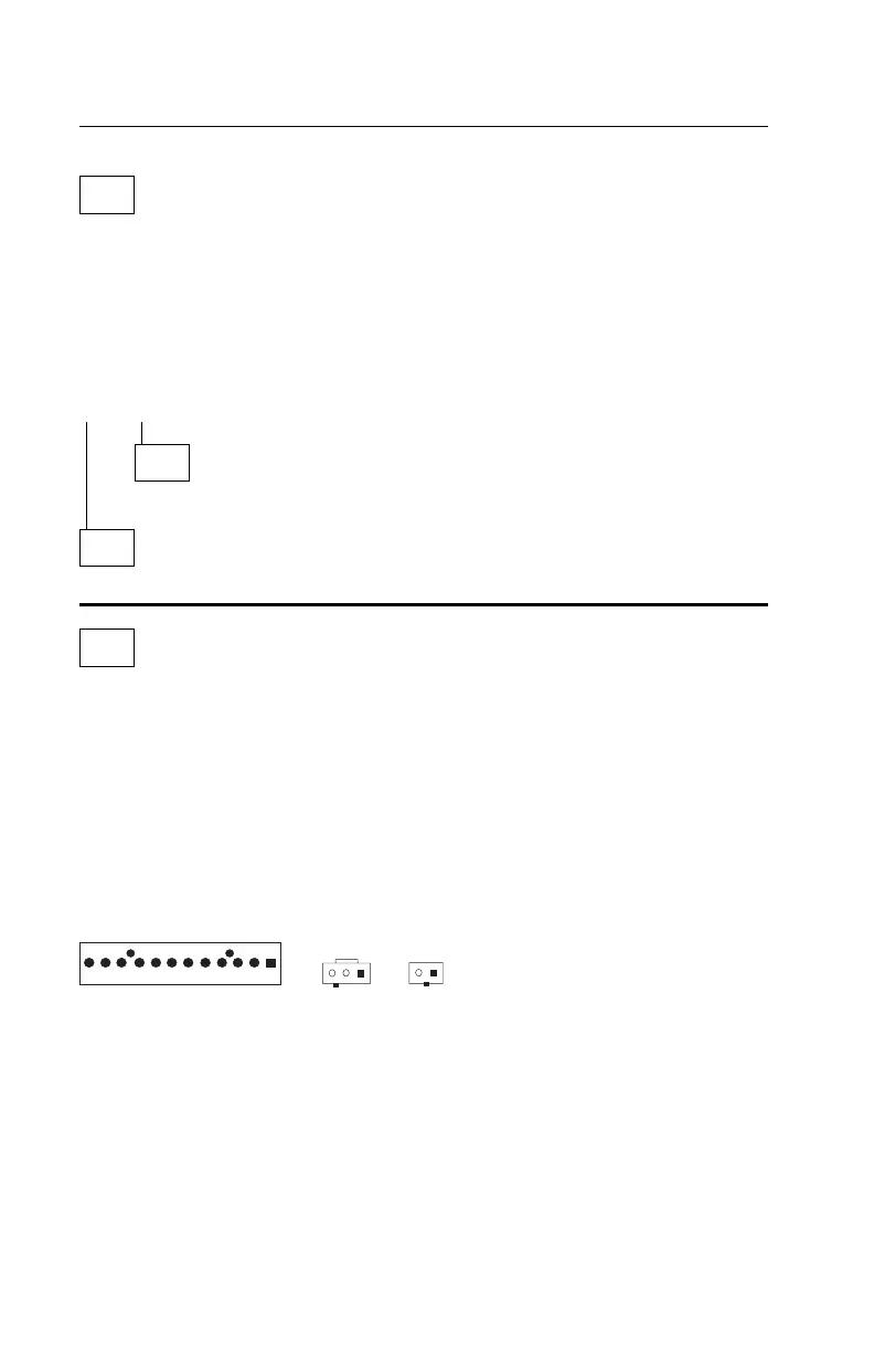
– Disconnect the power and switch cable connectors (J8, J29, and J30)
from the system board.
– Disconnect the power connectors to all drives.
J8
Cable Connectors
12 1
J29
1
J30
1
Figure 2-1. Power Connectors J8 and J30, Switch Connector J29 on
System Board
– Make a connection between (jumper) pins 2 and 3 on the cable connector
J30 (see “System Board Layout—Type I-1” on page 5-2 and “System
Board Layout—Type I-2” on page 5-5 for location).
(Step 004 continues)
2-26
 Loading...


