004 (continued)
Note: A paper clip may be used as a jumper.
123
Figure 2-2. Connector J30 on System Board
– Reconnect the power cord.
DOES THE POWER SUPPLY FAN RUN?
Yes No
005
Replace the power supply.
006
(From step 010)
– With the system powered on and the fan running, disconnect the power
and switch cables from the system board (J8, J29, and J30).
– Check the voltages at the power supply connectors for the system board
and all drive connectors, as shown in the following figures.
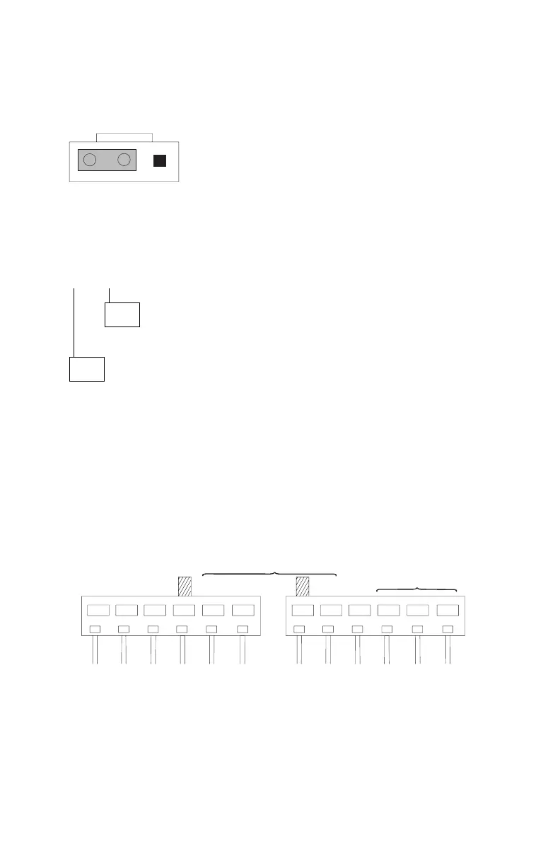
– PWR GOOD
– +3.75 to 6.25 V dc
– +9 to 15 V dc
– -9 to -15 V dc
GND
– -3.75 to -6.25 V dc
– +3.75 to 6.25 V dc
Pin
1
Pin
12
Figure 2-3. System Board Power Supply Connectors (J8 Bottom View)
Check Procedures 2-27
 Loading...


