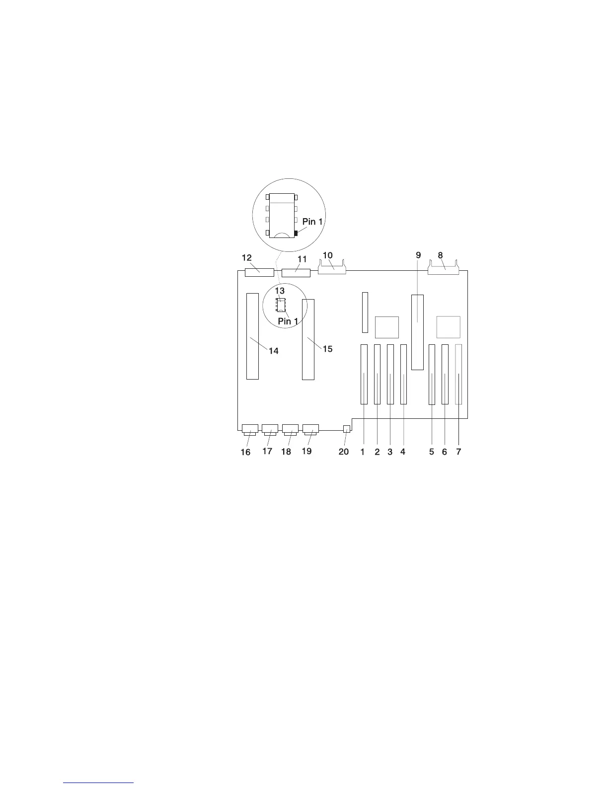
Model D20 I/O Backplane Locations
The following illustration of the I/O backplane identifies the primary connectors used in
your subsystem.
Note: Before replacing the I/O backplane, note the position of pin 1 on the VPD
module.
1 PCI-X Adapter Connector 1 11 Disk Drive Power Connector
2 PCI-X Adapter Connector 2 12 Cooling Blower Connector
3 PCI-X Adapter Connector 3 13 VPD Module
Attention: Note the location of Pin 1 before
removing.
4 PCI-X Adapter Connector 4 14 Redundant Power Supply Connector
5 PCI-X Adapter Connector 5 15 Primary Power Supply Connector
6 PCI-X Adapter Connector 6 16 Connector J11 (Not Used)
7 PCI-X Adapter Connector 7 17 Connector J14 (Not Used)
8 Operator Panel Connector 18 Connector J15 System Power Control Network
(SPCN) Connector
9 RIO Bus Adapter Connector 19 Connector J16 System Power Control Network
(SPCN) Connector
10 Disk Drive System Power Control Network
(SPCN) Connector
20 4-pin Connector, Rack Beacon Connector
Chapter 1. Reference Information
23