Notes:
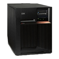
1. The FC 9079 base I/O tower contains two system PCI busses.
2. In the FC 9079 base I/O tower FRU locations and failing components table, the first of the two busses
in the tower is ″0001″ and the second bus in the tower is designated as ″yyyy″.
3. In FC 9079 Base I/O Towers, the bus connected to card positions C01 - C04 is bus number 0001. The
other bus in FC 9079 Base I/O Towers is not required to be in order.
4. Card position C01 is required to be an I/O processor.
5. Card positions C05 and C11 are required to be either I/O processors or Integrated xSeries
(TM)
Servers
(IXS).
6. J11 is an RPO connection, J14 is a uninterruptable power supply connector, J15 is an SPCN 1
connector, and J16 is an SPCN 2 connector.
Analyze hardware problems 277
 Loading...


