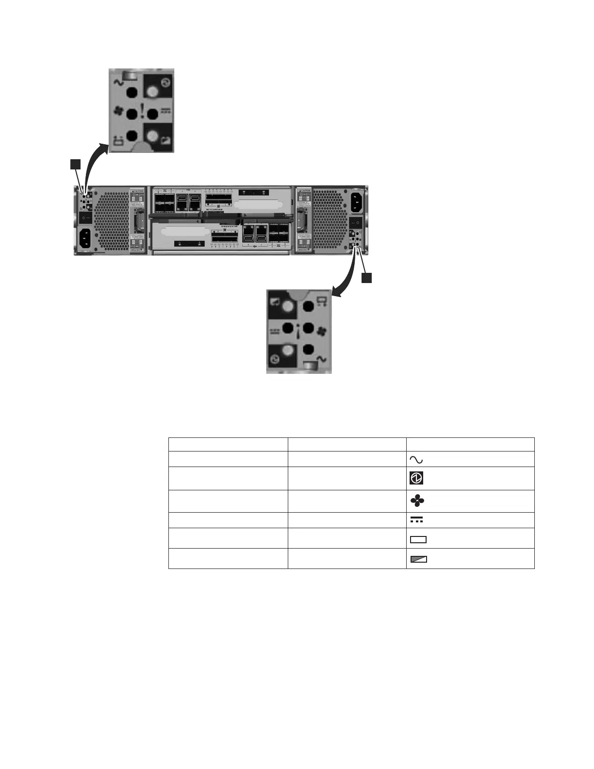
Table 6 identifies the LEDs in the rear of the control enclosure.
Table 6. Power supply unit LEDs in the rear of the control enclosure
Name Color Symbol
ac power failure Amber
Power supply OK Green
Fan failure Amber
dc power failure Amber
Battery failure Amber
+
-
Battery state Green
+
-
See “Procedure: Understanding the system status using the LEDs” on page 49 for
help in diagnosing a particular failure.
Power supply unit for the expansion enclosure
The expansion enclosure contains two power supply units.
The two power supply units in the enclosure are installed with one unit top side
up and the other inverted. The power supply unit for the expansion enclosure has
four LEDs, two less than the power supply for the control enclosure.
svc00670
1
1
Figure 10. LEDs on the power supply units of the control enclosure
Chapter 1. Storwize V7000 hardware components 7

 Loading...


