Table 11. 10 Gbps Ethernet port LEDs
Name Description Color
Link speed The LED is on when there is a link
connection; otherwise, the LED is off.
Amber
Activity The LED is flashing when there is activity on
the link; otherwise, the LED is off.
Green
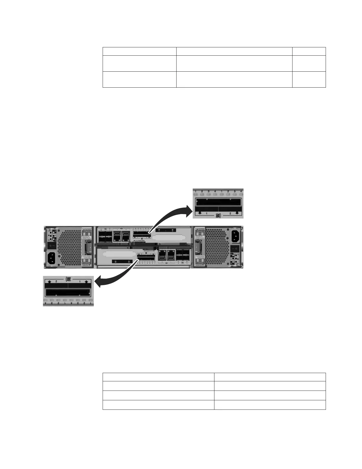
Node canister SAS ports and indicators
Two serial-attached SCSI (SAS) ports are located side by side in the rear of the
node canister.
The SAS ports are numbered 1 on the left and 2 on the right as shown in Figure 17.
Port 1 is used if you add one expansion enclosure. Port 2 is used if you add a
second expansion enclosure. Each port provides four data channels.
Note: The reference to the left and right locations applies to canister 1, which is
the upper canister. The port locations are inverted for canister 2, which is the lower
canister.
SAS ports must be connected to Storwize V7000 enclosures only. See “Problem:
SAS cabling not valid” on page 44 for help in attaching the SAS cables.
Four LEDs are located with each port. Each LED describes the status of one data
channel within the port. The data channel number is shown with the LED.
Table 12. SAS port LEDs on the node canister
LED state Description
Off No link is connected.
Flashing The link is connected and has activity.
On The link is connected.
svc00692
Figure 17. SAS ports on the node canisters.
Chapter 1. Storwize V7000 hardware components 13

 Loading...


