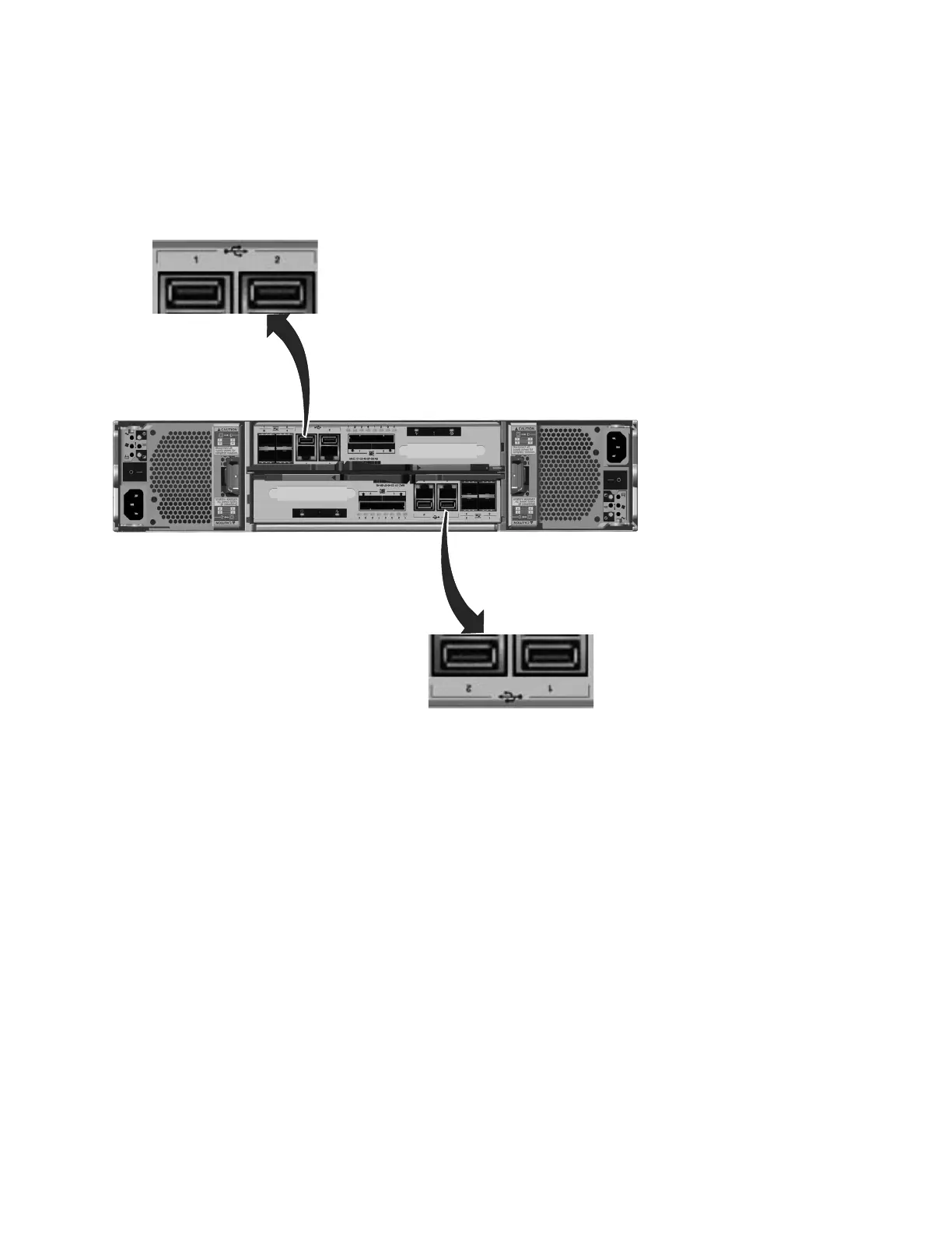
The USB ports are numbered 1 on the left and 2 on the right as shown in
Figure 14. One port is used during installation.
Note: The reference to the left and right locations applies to canister 1, which is
the upper canister. The port locations are inverted for canister 2, which is the lower
canister.
The USB ports have no indicators.
Ethernet ports and indicators
Ethernet ports are located side by side on the rear of the node canister. All control
enclosure models have two 1 Gbps Ethernet ports per node canister. Model
2076-312 and model 2076-324 also have two 10 Gbps Ethernet ports per node
canister.
For the 1 Gbps support, the Ethernet ports are numbered 1 on the left and 2 on the
right as shown in Figure 15 on page 12. Port 1 must be connected; the use of port 2
is optional. Two LEDs are associated with each port.
Note: The reference to the left and right locations applies to canister 1, which is
the upper canister. The port locations are inverted for canister 2, which is the lower
canister.
svc00690
Figure 14. USB ports on the node canisters
Chapter 1. Storwize V7000 hardware components 11

 Loading...


