Note: The drawer sensor should switch pin 6 to pin 3 when the drawer is open.
EIA-232 connector pin assignments
SureMark printers contain a 9-pin D-shell connector port for EIA-232
communication. This port is on the interface card, accessible under the printer
without removing printer covers. The connector has the following pin functions:
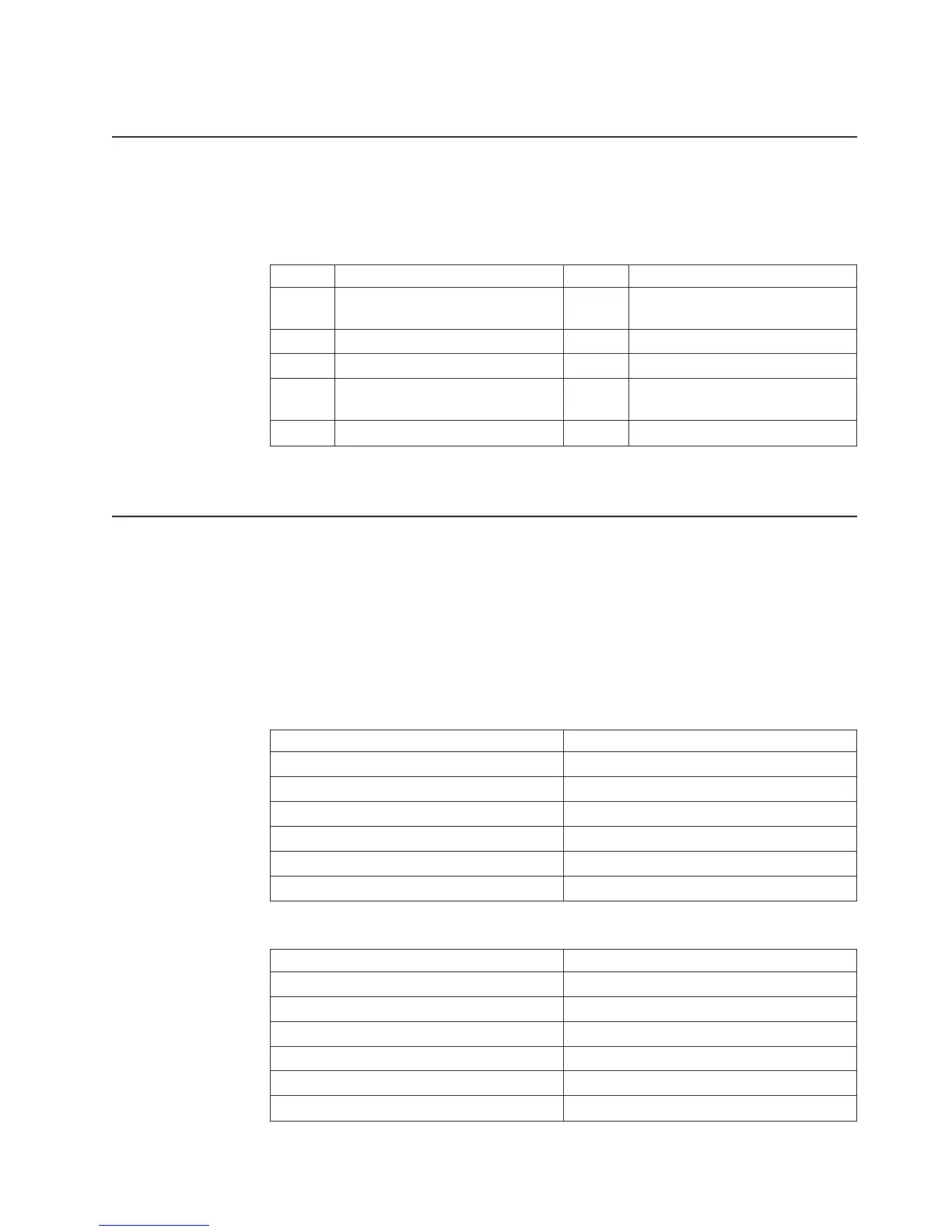
Table 8. EIA-232 connector pin functions
Pin Signal Pin Signal
1 Not Connected 6 DSR (Not connected on 3-wire
cable)
2 Transmit 7 Not Connected
3 Receive 8 RTS
4 DTR (Not connected on 3-wire
cable)
9 Not Connected
5 Signal Ground
See “Description of models” on page 4 for the cable part number.
EIA-232 parameters
Protocol
DTR/DSR mode or XON/XOFF mode. Dip switch selectable.
Baud rate
9600 or 19 200 kbps. Dip switch selectable.
Start 1 bit
Data 8 bits
Parity None
Stop 1 bit
Table 9. 9-pin to 9-pin EIA-232 connector layout
System Description Printer Description
Pin2-Rx(input) Pin 2- Tx (Output)
Pin 3 - Tx (Output) Pin3-Rx(Input)
Pin 4 - DTR (Output) Pin 4 - DTR (Input)
Pin 5 - Gnd Pin 5 - Gnd
Pin 6 - DSR (Input) Pin 6 - DSR (Output)
Pin 8 - CTS (Input) Pin8-RTS(Output)
Table 10. 25-pin to 25-pin EIA-232 connector layout
System Description Printer Description
Pin 2 - Tx (Output) Pin3-Rx(Input)
Pin3-Rx(Input) Pin 2 - Tx (Output)
Pin 5 - CTS (Input) Pin8-RTS(Output)
Pin 6 - DSR (Input) Pin 6 - DSR (Output)
Pin 7 - Gnd Pin 5 - Gnd
Pin 20 - DTR (Output) Pin 4 - DTR (Input)
Updated April 2, 2009
Appendix C. Technical information 91