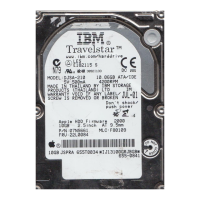
Table 1. Internal component descriptions
Number Component Description
1 Cartridge
magazine
The tape library has a single cartridge magazine that can hold up to nine data cartridges, or eight data cartridges with a 1-slot I/O
station.
Column 5/Tier 1 in the cartridge magazine can be configured as a 1-slot I/O station. Column 5/Tier 2 in the cartridge magazine is
reserved for the exchange position and can be accessed by the library only. The I/O station is used to import and export cartridges
without interrupting normal library operation. Beginning with Column 4, a minimum of one column can be reserved for cleaning
cartridges. Cleaning cartridges are used to clean the tape drive heads. For more information, see Physical library settings.
2 accessor This component contains the library robot and bar code reader. The accessor moves cartridges to/from:
I/O station
Storage slots
Tape drive
3 Library control
board
The library control board manages the entire library, including the Operator Panel and accessor, and is responsible for monitoring
the library to ensure that the library is functioning properly. It stores vital product data (VPD) such as library settings, serial number,
library logs, and accessor calibration backup data.
4 Power® supply The power supply is the sole source of power for the library.
5 Tape Drive The library supports the Ultrium 3, 4, 5, 6, 7, 8, and 9 half-height tape drive.
Removing the tape drive from the library
To remove the SAS tape drive from the library, complete the following steps:
1. Turn OFF the power to the library.
2. Disconnect all cables from the rear panel of the library.
3. Remove the library cover. See Removing or reinstalling the library chassis cover.
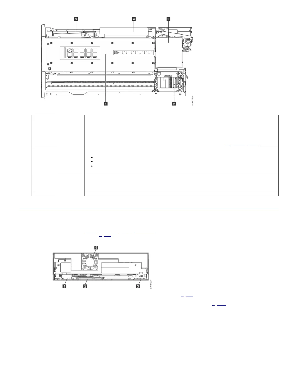
4. Disconnect the internal SAS cable (2 in Figure 9).
Figure 9. Rear panel of the SAS Half-Height drive
5. If connected, disconnect the internal LDI (RS-422) cable from the LDI (RS-422) connector (3 in Figure 9).
6. Remove the cartridge magazine from the library.
7. Remove the drive mounting screws from the sides of the tape drive housing. Two screws are on each side of the drive (Figure 10).
Figure 10. Drive housing screw locations
 Loading...