92
10
CONNECTIONS AND MAINTENANCE
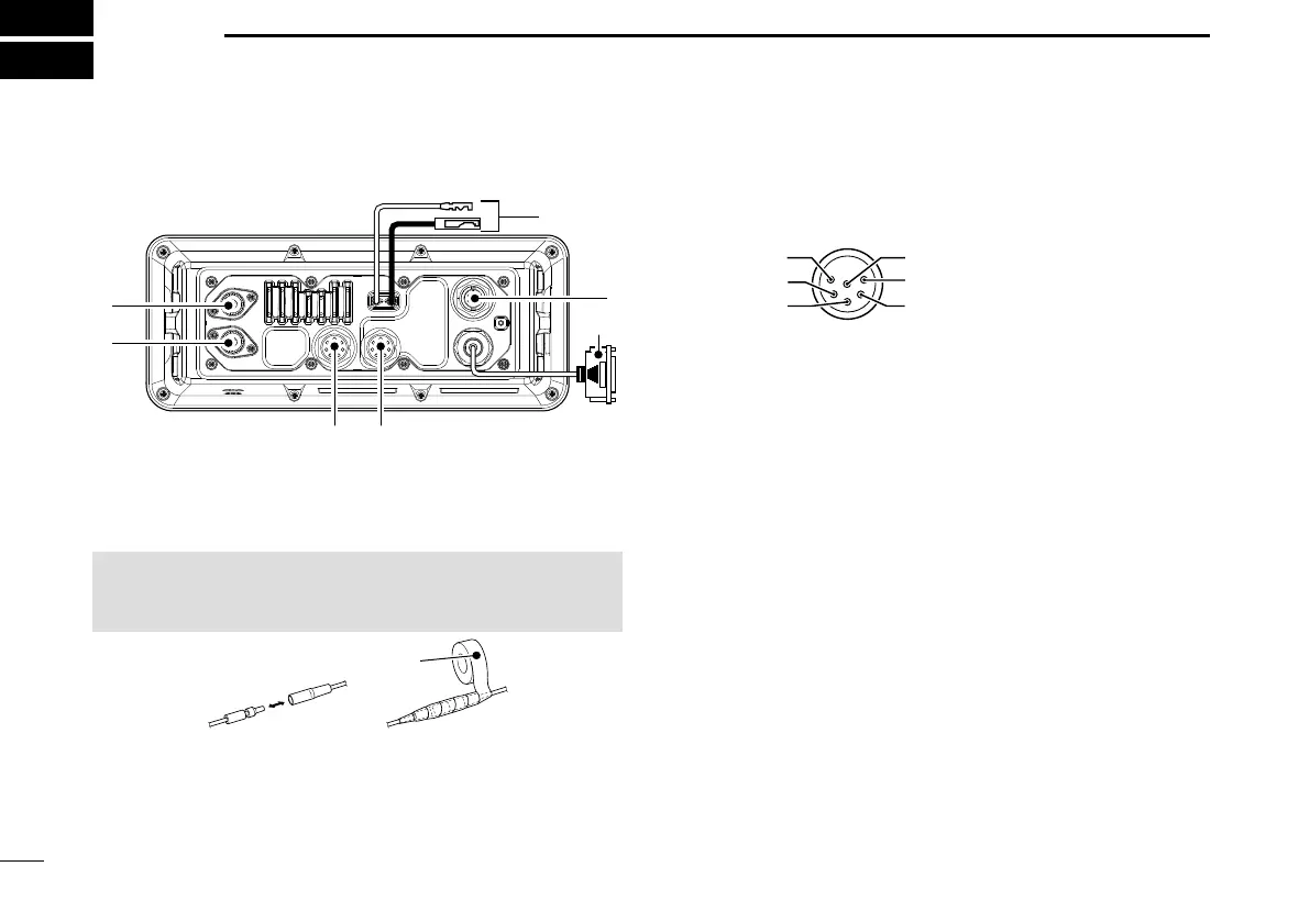
■ Connections
e D-SUB 25-PIN
Connects to a printer (IBM
®
centronics or compatible) to
print out the received DSC call contents.
q
e
t r
w EXTERNAL SPEAKER/VDR CONNECTOR
Connects to a voice recorder or an external speaker.
Use the supplied accessory connector for connections.
See page 95 for details.
SP (+)
SP (–)
NC
NC
VDR* (–)
VDR* (+)
*VDR: Voyage Data
Recorder
CAUTION: After connecting the DC power cable, cover the
connector with a tape, as shown below, to prevent water
seeping into the connection.
q DC POWER CONNECTOR
Connects the PS-310 with the DC power cable of the
PS-310. (p. 96)
Rubber vulcanizing tape
r REMOTE ALARM CONNECTOR
Use the supplied accessory connector for connections. See
page 95 for details.
Remote alarm output terminal
• 4 V DC*
• Maximum 10 mA*
* When the external equipment is connected between this terminal
and the GND terminal.
When DSC call that is related to “Distress” as described below
is received, 4 V DC is output and the key backlight blinks.
• Distress call
• Distress acknowledgment
• Distress Relay call
• Distress Relay acknowledgment
• Distress Cancel call
• DSC call whose category is “Distress”
• Lead: Thicker than 0.75 sq mm,
Length: Shorter than 1.5 m is recommended.