4-5
4-2 TRANSMIT CIRCUITS
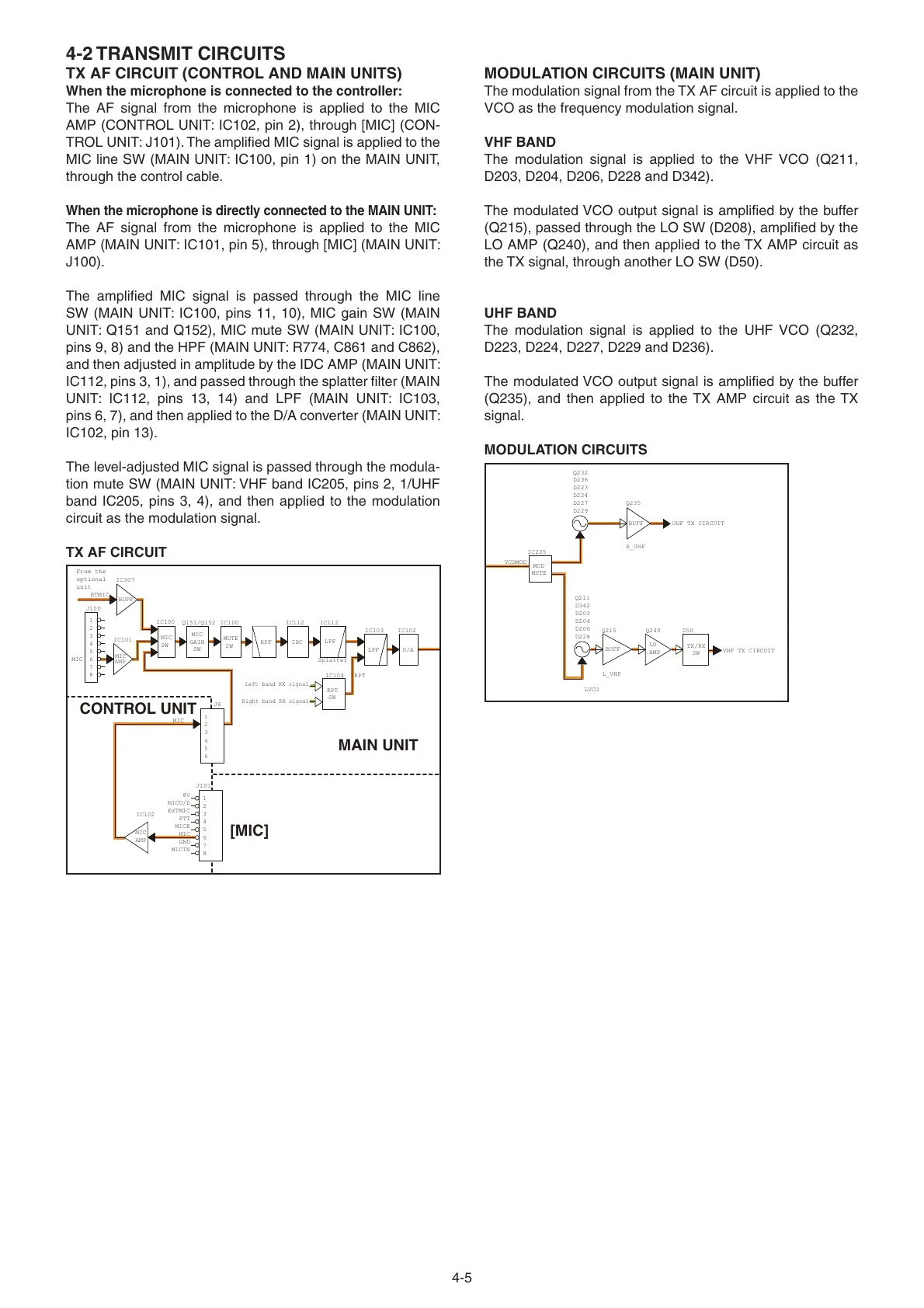
TX AF CIRCUIT (CONTROL AND MAIN UNITS)
When the microphone is connected to the controller:
The AF signal from the microphone is applied to the MIC
AMP (CONTROL UNIT: IC102, pin 2), through [MIC] (CON-
TROL UNIT: J101). The amplifi ed MIC signal is applied to the
MIC line SW (MAIN UNIT: IC100, pin 1) on the MAIN UNIT,
through the control cable.
When the microphone is directly connected to the MAIN UNIT:
The AF signal from the microphone is applied to the MIC
AMP (MAIN UNIT: IC101, pin 5), through [MIC] (MAIN UNIT:
J100).
The amplifi ed MIC signal is passed through the MIC line
SW (MAIN UNIT: IC100, pins 11, 10), MIC gain SW (MAIN
UNIT: Q151 and Q152), MIC mute SW (MAIN UNIT: IC100,
pins 9, 8) and the HPF (MAIN UNIT: R774, C861 and C862),
and then adjusted in amplitude by the IDC AMP (MAIN UNIT:
IC112, pins 3, 1), and passed through the splatter fi lter (MAIN
UNIT: IC112, pins 13, 14) and LPF (MAIN UNIT: IC103,
pins 6, 7), and then applied to the D/A converter (MAIN UNIT:
IC102, pin 13).
The level-adjusted MIC signal is passed through the modula-
tion mute SW (MAIN UNIT: VHF band IC205, pins 2, 1/UHF
band IC205, pins 3, 4), and then applied to the modulation
circuit as the modulation signal.
TX AF CIRCUIT
D/A
Splatter
LPF
HPF
J100
1
2
3
4
5
6
7
8
LPF
IDC
MIC
AMP
BUFF
MIC
GAIN
SW
J101
1
2
3
4
5
6
7
8
MIC
AMP
MUTE
SW
MIC
RPT
RPT
Left band RX signal
Right band RX signal
SW
BTMIC
From the
optional
unit
5
3
6
1
4
2
CONTROL UNIT
MAIN UNIT
[MIC]
J6
IC307
Q151/Q152
IC101
IC112IC100 IC112
IC104
IC103 IC102
MIC
MIC
8V
MICE
PTT
MICIN
EXTMIC
IC102
GND
MICU/D
MIC
SW
IC100
MODULATION CIRCUITS (MAIN UNIT)
The modulation signal from the TX AF circuit is applied to the
VCO as the frequency modulation signal.
VHF BAND
The modulation signal is applied to the VHF VCO (Q211,
D203, D204, D206, D228 and D342).
The modulated VCO output signal is amplifi ed by the buffer
(Q215), passed through the LO SW (D208), amplifi ed by the
LO AMP (Q240), and then applied to the TX AMP circuit as
the TX signal, through another LO SW (D50).
UHF BAND
The modulation signal is applied to the UHF VCO (Q232,
D223, D224, D227, D229 and D236).
The modulated VCO output signal is amplifi ed by the buffer
(Q235), and then applied to the TX AMP circuit as the TX
signal.
MODULATION CIRCUITS
LO
AMP
BUFF
BUFF
TX/RX
SW
VCOMOD
MOD
MUTE
R_UHF
L_VHF
LVCO
IC205
Q215
Q211
Q240
Q232
Q235
D50
D223
D224
D203
D204
D206
D227
D229
D342
D228
D236
UHF TX CIRCUIT
VHF TX CIRCUIT