5-1
SECTION 5. ADJUSTMENT PROCEDURE
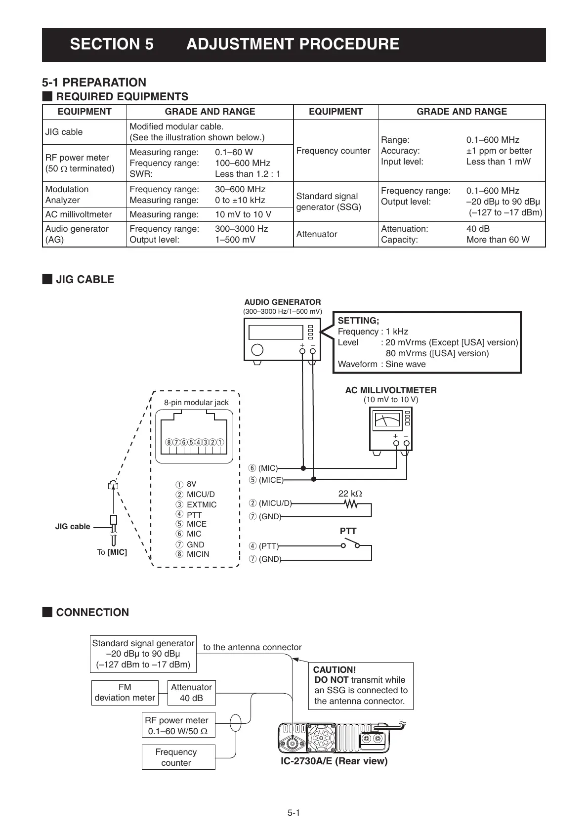
M CONNECTION
M JIG CABLE
M REQUIRED EQUIPMENTS
EQUIPMENT GRADE AND RANGE EQUIPMENT GRADE AND RANGE
JIG cable
Modifi ed modular cable.
(See the illustration shown below.)
Frequency counter
Range: 0.1–600 MHz
Accuracy: ±1 ppm or better
Input level: Less than 1 mW
RF power meter
(50
terminated)
Measuring range: 0.1–60 W
Frequency range: 100–600 MHz
SWR: Less than 1.2 : 1
Modulation
Analyzer
Frequency range: 30–600 MHz
Measuring range: 0 to ±10 kHz
Standard signal
generator (SSG)
Frequency range: 0.1–600 MHz
Output level: –20 dBµ to 90 dBµ
(–127 to –17 dBm)
AC millivoltmeter Measuring range: 10 mV to 10 V
Audio generator
(AG)
Frequency range: 300–3000 Hz
Output level: 1–500 mV
Attenuator
Attenuation: 40 dB
Capacity: More than 60 W
5-1 PREPARATION
8-pin modular jack
q
i
u
ytre
w
q
w
e
r
t
y
u
i
8V
MICU/D
EXTMIC
PTT
MICE
MIC
GND
MICIN
y (MIC)
w (MICU/D)
u (GND)
r (PTT)
u (GND)
t (MICE)
AUDIO GENERATOR
(300–3000 Hz/1–500 mV)
+−
22 kΩ
+−
AC MILLIVOLTMETER
(10 mV to 10 V)
PTT
JIG cable
To [MIC]
SETTING;
Frequency : 1 kHz
Level : 20 mVrms (Except [USA] version)
80 mVrms ([USA] version)
Waveform : Sine wave
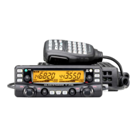
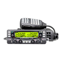
IC-2730A/E (Rear view)
FM
deviation meter
to the antenna connector
Attenuator
40 dB
RF power meter
0.1–60 W/50 Ω
Frequency
counter
Standard signal generator
–20 dBµ to 90 dBµ
(–127 dBm to –17 dBm)
DO NOT transmit while
an SSG is connected to
the antenna connector.