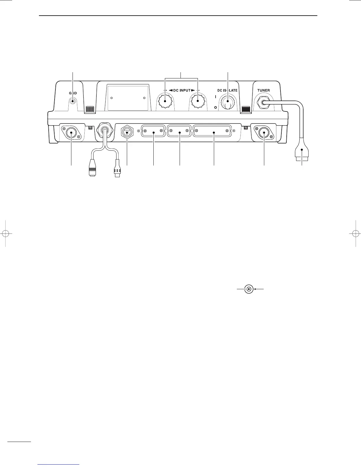
■ Main unit
q
GROUND TERMINAL
IMPORTANT! Connects a ship’s ground. See
page 51 for details.
w DC POWER TERMINALS (pgs. 49, 52)
Accepts 12 V DC or 24 V DC through the supplied
DC power cables.
Red terminal is for positive and black terminal is for
negative connection.
e DC ISOLATE SWITCH [DC ISOLATE] (p. 49)
Turns the transceiver’s main power ON and OFF.
r TUNER CONTROL SOCKET (pgs. 49, 52)
Connects a control cable to an optional antenna
tuner.
A female connector kit is supplied for external an-
tenna tuner connection.
t ANTENNA CONNECTOR 1 (pgs. 49, 52)
Connects a 50 Ω HF band antenna via a 50 Ω
matched coaxial cable with a PL-259 plug for both
transmit and receive operation.
y PRINTER CONNECTOR (pgs. 50, 60)
Connects an IBM
®
centronics or compatible printer
to print out received DSC information automatically
or manually.
u REMOTE CONNECTOR [REMOTE] (pgs. 50, 59)
Connects to a PC via an RS-232C cable (D-sub 9-
pin) for remote control in the NMEA or RS-232C for-
mat.
i MODEM CONNECTOR [AF/MOD] (pgs. 50, 59)
Connects to an NBDP (Narrow Band Direct Print-
ing) or FAX system via a D-sub 9-pin cable.
o CONTROLLER CONNECTOR [CONTROLLER]
(p. 49)
Connects the supplied remote controller, RC-25E.
!0 GPS CONNECTOR [GPS] (p. 50)
Input position and UTC data (NMEA0183 ver. 3.01
format), such as from a GPS receiver, etc., for set-
ting your positioning and time data automatically
without manual input for DSC operation.
!1 SPEAKER JACK [SP] (p. 49)
Connects the supplied external speaker, SP-24E.
!2 ANTENNA CONNECTOR 2 (p. 49)
Connects a 50 Ω HF band antenna via a 50 Ω
matched coaxial cable with a PL-259 plug for DSC
receiver.
NMEA IN (+)
RCA
NMEA IN (–)
4
2
PANEL DESCRIPTION
2001 NEW 2001 NEW
IC-M801E_0.qxd 05.12.2 16:32 Page 4