■
Connector information (continued)
60
12
CONNECTION AND INSTALLATION
2001 NEW
REMOTE Pin Pin name Description
1 STROBE Outputs a strobe pulse after data output.
2–9DATA1–8 Outputs 8-bit parallel data.
10 ACKNLG
Input port for the connected printer.
“Low” pulse signal is applied from the printer during the printer accepts data input.
Input port for the connected printer.
11 BUSY “High” level signal is applied from the printer during the printer cannot accept data
input, such as when off line.
12–14 NC No connection.
15 ERROR
Input port for the connected printer.
The printer output becomes “Low” when an printer error, such as no paper, occurs.
16, 17 NC No connection.
18–25 GND Ground terminals.
13..........................1
25......................14
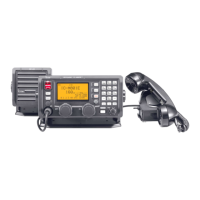
Front panel view
IC-M801E_0.qxd 05.12.2 16:33 Page 60


 To Next Page