2: P
RODUCT
S
PECIFICATIONS
2-132 FC6A S
ERIES
MICROS
MART
U
SER
’
S
M
ANUAL
FC9Y-B1722
*1 The resistance (allowable conductor resistance) of the electrical leads to connect to the resistance thermometer is 10 Ω or less per wire.
*2 The arbitrary setting is a function that uses the digital resolution data by scaling it to arbitrary data (that arbitrarily sets the lower limit value and
the upper limit value). The range setting (-32,768 to 32,767) is specified with data registers.
Example: When -5 V is input, 1,024 is displayed as long as the arbitrary setting is not configured, but -500 is displayed when the arbitrary
setting is configured as upper limit value = 1,000 and lower limit value = -1,000, and this makes it easier to intuitively read the input
voltage value.
*3 Input data out of range is reflected in the status of the analog I/O module.
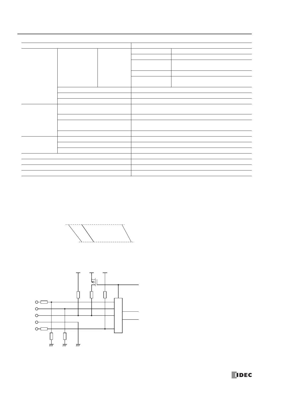
Input Internal Circuit
Data
Input Value per
Step
Resistance
Thermometer
Type Input Value per Step
Pt100 1°C (°F)
Pt100 (with decimal
point)
0.1°C (°F)
JPt100 1°C (°F)
JPt100 (with decimal
point)
0.1°C (°F)
Data Type in Application Program Can be arbitrarily set for each CH in a range between -32,768 to 32,767
*2
Monotonicity Yes
Input Data Out of Range Detectable
*3
Noise Resistance
Maximum Temporary Deviation
during Electrical Noise Tests
±4% or less of full scale
Input Filter Yes
Recommended Cable for Noise
Immunity
Current/voltage: Pair shielded cable
Other: Pair cable
Crosstalk None
Isolation
Between Input and Power Circuit Transformer isolated
Between I/O and Internal Circuit Photocoupler isolated
Between Inputs Photocoupler isolated
Effect of Improper Input Connection No damage
Maximum Permanent Allowed Overload (No Damage) 15V DC or lower (0 to 1 V range is 5V DC or lower), 50 mA or lower
Selection of Input Type and Input Range Using programming software
Calibration or Verification to Maintain Rated Accuracy Not possible
Type No. FC6A-F2M1, FC6A-F2M4, FC6A-F2MR1, FC6A-F2MR4
Lower Limit Value=-1,000 -500
Raw Input Value
Input Voltage Value
1,024
-5 V
4,095
10 V
0
-10 V
Upper Limit Value=1,000
When the digital resolution data is 12 bits and the input range is -10 to +10
Multiplexer
5 V ≤
2 MΩ
39 kΩ
10 Ω
mA
+(A)
–
(B)
(B)
Input
Switching Signal

 Loading...