FC6A S
ERIES
MICROS
MART
U
SER
’
S
M
ANUAL
FC9Y-B1722 2-57
2: P
RODUCT
S
PECIFICATIONS
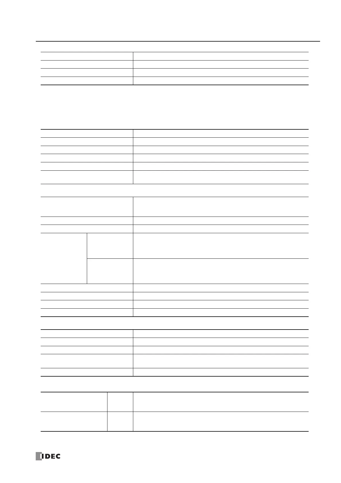
Run/Stop Methods
USB Port
Ethernet Port
SD Memory Card Slot
Communication Connector
*1 All devices that are connectable to the communication connector cannot be used in expanded ambient operating temperatures (-25 to -10°C
and 55 to 65°C). Do not connect these devices when the product is used in expanded ambient operating temperatures.
Input Delay Time 12 ms (including the software filter)
Maximum Allowed Steady Load 13 V
Isolation Not isolated
Cable Unshielded cable 1 m (included with the product)
Power on/off
WindLDR RUN/STOP command
Function switch operation
Special internal relay (M8000) operation
Operation of stop input and reset input
Points 1
Communication Type USB2.0 Full speed, CDC class
Communication Functions Capable of maintenance communication with a PC
Connector USB mini-B
Isolation between Internal Circuit Not isolated
Available Function when FC6A is
Powered by USB
Downloading/uploading user programs, downloading system software, data file manager
Points
2
(When the HMI module is connected, this can be expanded by 1 point with the Ethernet
port that has the web server function.)
Communication Type IEEE 802.3 compliant
Communication Speed 10BASE-T, 100BASE-TX
Communication
Functions
Port 1
Maintenance communication server,
User communication server/client (TCP/UDP),
Modbus TCP server/client,
PING, SNTP, e-mail, web server, FTP server/client, BACnet/IP
Port 2
Maintenance communication server,
User communication server/client (TCP/UDP),
Modbus TCP server/client,
PING, EtherNet/IP communication
Connector RJ45 (Auto MDI/MDI-X compatible)
Cable CAT 5 or higher, STP
Maximum Cable Length 100 m
Isolation between Internal Circuit Pulse transformer isolated
Points 1
Supported SD Card SD memory cards (max 2 GB), SDHC memory cards (max 32 GB)
File System FAT16, FAT32
Function
Downloading/uploading user programs, saving log data,
recipes, downloading system software, saving web pages
Insertion/Removal Durability 2,000 times
Cartridge Base Module
Connection
*1
No. of
Modules
1
(Two cartridges can be connected to the cartridge base module when it is connected to the
Plus CPU module.)
HMI Module Connection
*1
No. of
Modules
1
(One cartridge can be connected to the HMI module when it is connected to the Plus CPU
module.)

 Loading...