MorphoWave Compact - 2018_2000035853-v81
4.9 > Ethernet connection
Use a category 6 shielding cable (120 Ohms) or better. It is strongly recommended to insert a repeater
unit every 90 m.
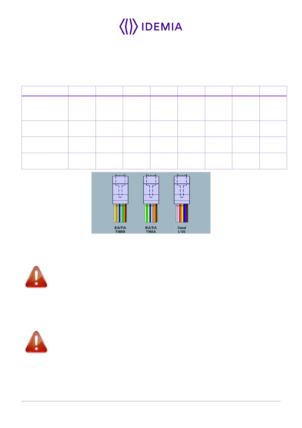
Recommendations for RJ45 wiring
Ground/
pin
dedicated
(-)
Figure 33: RJ45 wiring
RJ45 plug pinout is compliant with 10/100 base T, IEEE802.3 Specification. Product is compliant also with
MDI or MDI-X.
Ethernet cable shall be shielded
Ethernet interface can be used to power the MorphoWave SP terminal through PoE+ (Power Over Ethernet
Plus - IEEE802.3at type 2 mode). According to the PoE+ standard two modes are available: power on
data pins and power on dedicated pins.
Use either one of these modes depending on PoE+ implementation on your local Ethernet network.
Some functions are available ONLY with an external and not with PoE+ power supply:
Wi-Fi
™
, SAM, PIV/TWIC. External DC power is required for these features.
Default Ethernet configuration
By default, MorphoWave SP terminal is configured in STATIC mode with the following configuration: IP
Adress : 192.168.1.10; Gateway Adress : 192.168.1.254; Subnet Mask : 255.255.254.0