8 Installation, Support, and Maintenance Guide
Evolution X7 Satellite Router
X7 Router Front LEDs
3.1 X7 Router Front LEDs
The X7 Router front panel is shown in Figure 3-1 and defined in Figure 3-1.
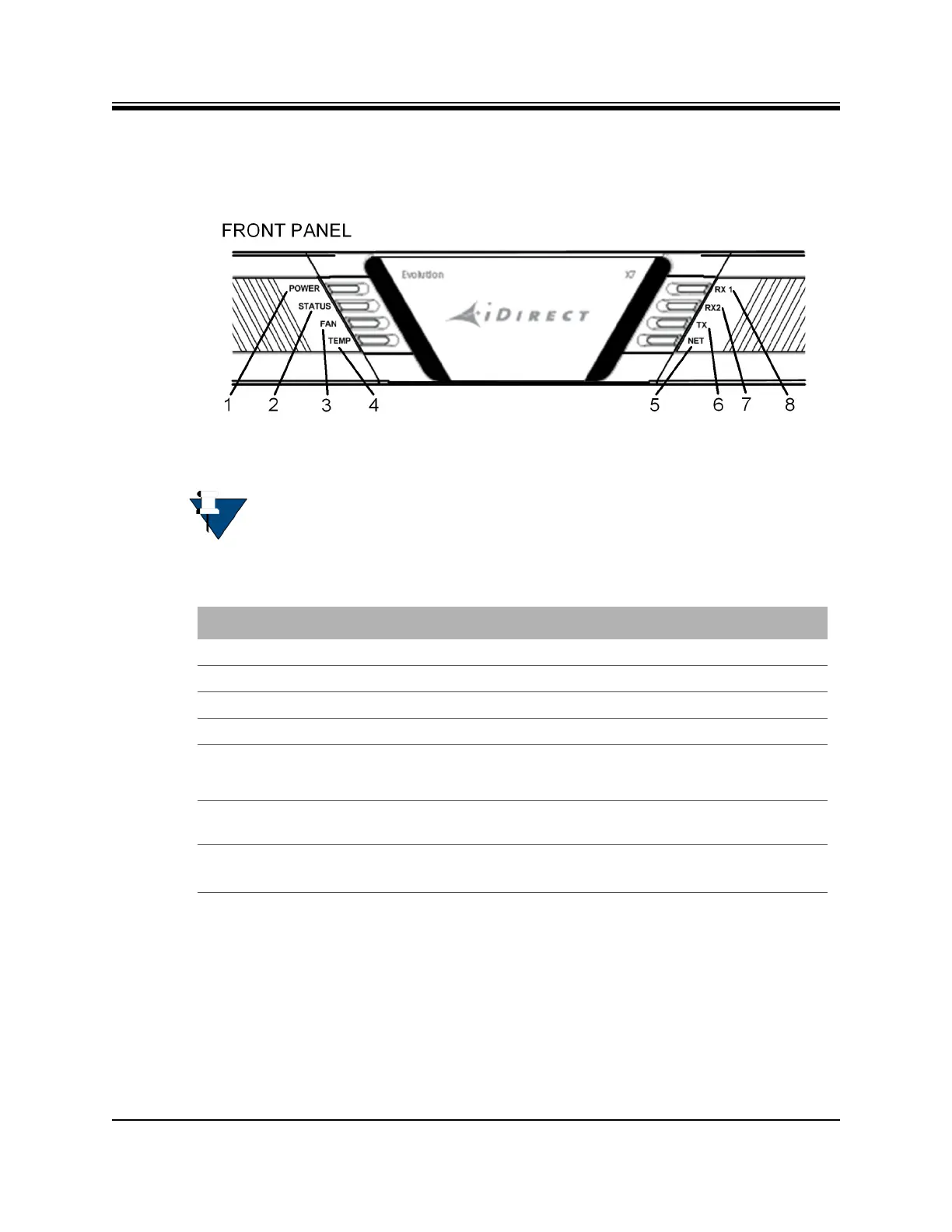
Figure 3-1. X7 Router Front Panel LED Display
NOTE: The descriptions of the LEDs may vary between iDX Software Releases.
Check the release specific iDX Satellite Router Installation and Commissioning
Guide, Web iSite User Guide, and iDX Release Notes for details.
Table 3-1. X7 Router Front Panel Description
1 - POWER Indicates power supply status and any power-related problems
2 - STATUS Indicates basic operational state and problems with core hardware
3 - FAN Provides fan status
4 - TEMP Indicates any problems with the current operating temperature
5 and 6 - RX1 and
7 - TX
3.2 X7 Front Panel LED Status Descriptions
Descriptions for states of LEDs may vary between iDX Software Releases. Check the release
specific iDX Satellite Router Installation and Commissioning Guide, Web iSite User Guide, and
Callout - Label Description
RX2 (future)
Provides downstream receive status, see Table 3-3 on page 11, callouts
12 and 14, for rear power receive status LED information
Indicates the state of the transmitter, see Table 3-3 on page 11 ,
callout 9, for BUC power LED information
8 - NET Modem Network Status: indicates the state of the satellite network
connection