Installation, Support, and Maintenance Guide 41
Evolution X7 Satellite Router
Appendix E DC Power
Supply Installation
This appendix describes the installation of the DC power supply wiring for Option 3.
Make sure all items are available to prepare the cable entry housing. Descriptions and
diagrams of the items included with the router or necessary for the DC wiring are found in
Table E-1. “At a Glance” instructions are in Figure E-1 on page 42 with corresponding detailed
steps in Table E-2 on page 42.
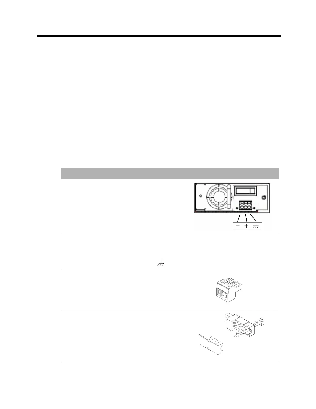
Table E-1. X7 Router DC Power Module Connector Parts
• red = positive +
• black = negative -
• blue = ground -
Name Description Diagram or Reference
DC Terminal block Rear panel, DC terminal block
area
3 DC input wires Appropriately labeled wires,
such as:
14-18 AWG (American Wire Gauge)
Reference:
http://en.wikipedia.org/wiki/American_
wire_gauge
Terminal block plug Included in kit, P/N Phoenix
1779848
Cable Entry Housing
Strain Relief and
Cable Tie
Cable Entry Housing Strain
Relief and Cable Tie, included
in kit, P/N 1803947, and cable
tie