DM-F Series Monitor
Page 70
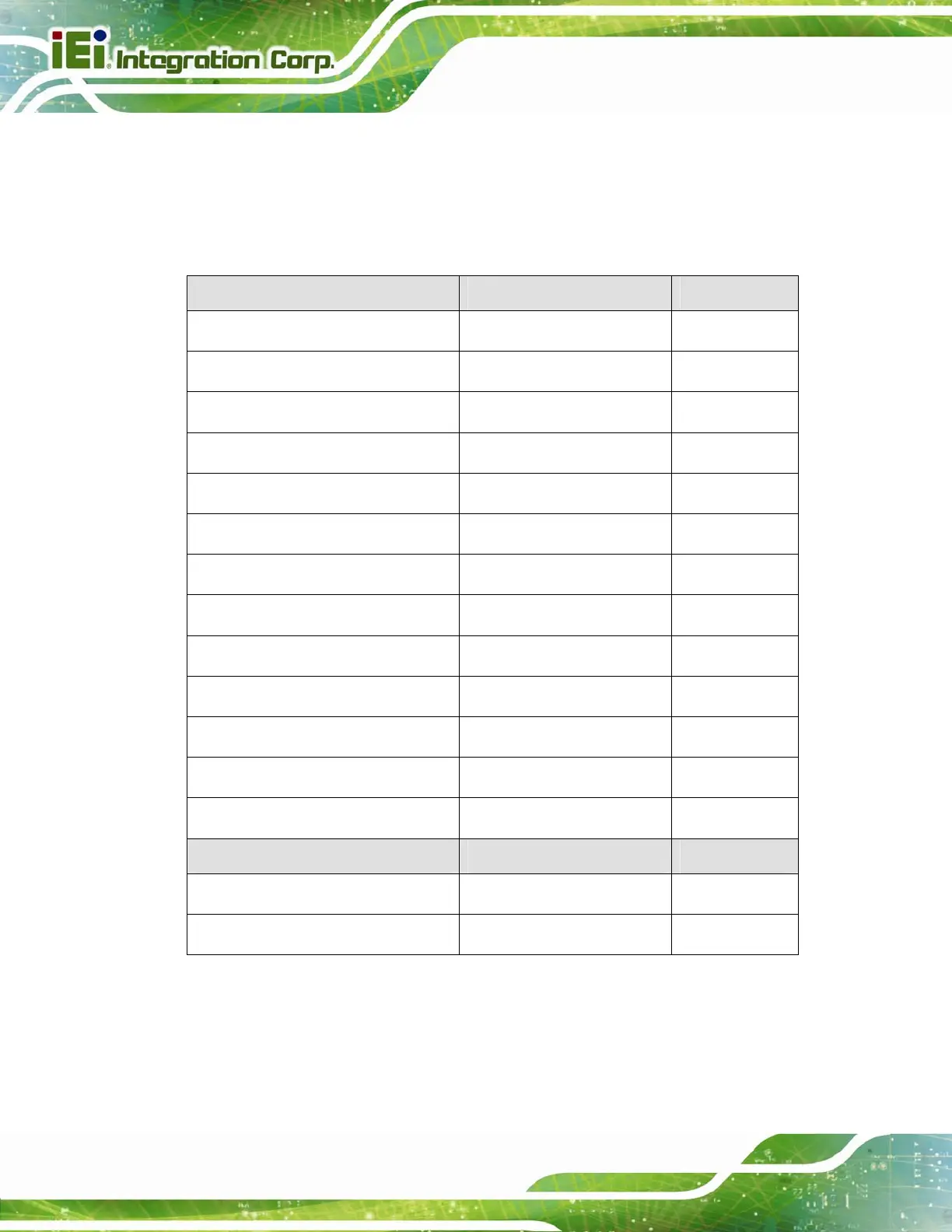
6.2.1 AV-6038 Peripheral Interface Connectors
5Table 6-1 shows a list of the peripheral interface connectors on the AV-6038 AD board.
Pinouts of the connectors that are used in the DM-F series can be found in the following
sections.
Connector Type Label
Backlight Inverter connector 6-pin wafer, p=2.00 mm INVERTER1
COM debug port connector 2-pin wafer, p=2.00 mm CN2
Camera connector 4-pin wafer, p=1.25 mm USB_CAM1
DisplayPort firmware connector 4-pin wafer, p=1.25 mm DP_FW1
HDMI firmware connector 4-pin wafer, p=1.25 mm HDMI_FW1
Infrared connector 2-pin wafer, p=2.00 mm CN3
LVDS connector 30-pin crimp, p=1.25 mm LVDS1
OSD keypad connector 12-pin wafer, p=1.00 mm CN14
Power input connector 4-pin wafer, p=3.96 mm CN9
RS-232 connector for touchscreen 6-pin wafer, p=1.25 mm RS232_1
SPI flash connector 6-pin wafer, p=1.25 mm JSPI1
USB connector for touchscreen 4-pin wafer, p=1.25 mm USB_TOUCH1
Touchscreen connector 9-pin wafer, p=1.25 mm J1
Jumper Type Label
LVDS panel voltage select jumper 6-pin header, p=2.54 mm JP2
EIDE firmware update jumper 2-pin header, p=2.00 mm JP3
Table 6-1: AV-6038 Peripheral Interface Connectors
 Loading...