DM-F Series Monitor
Page 74
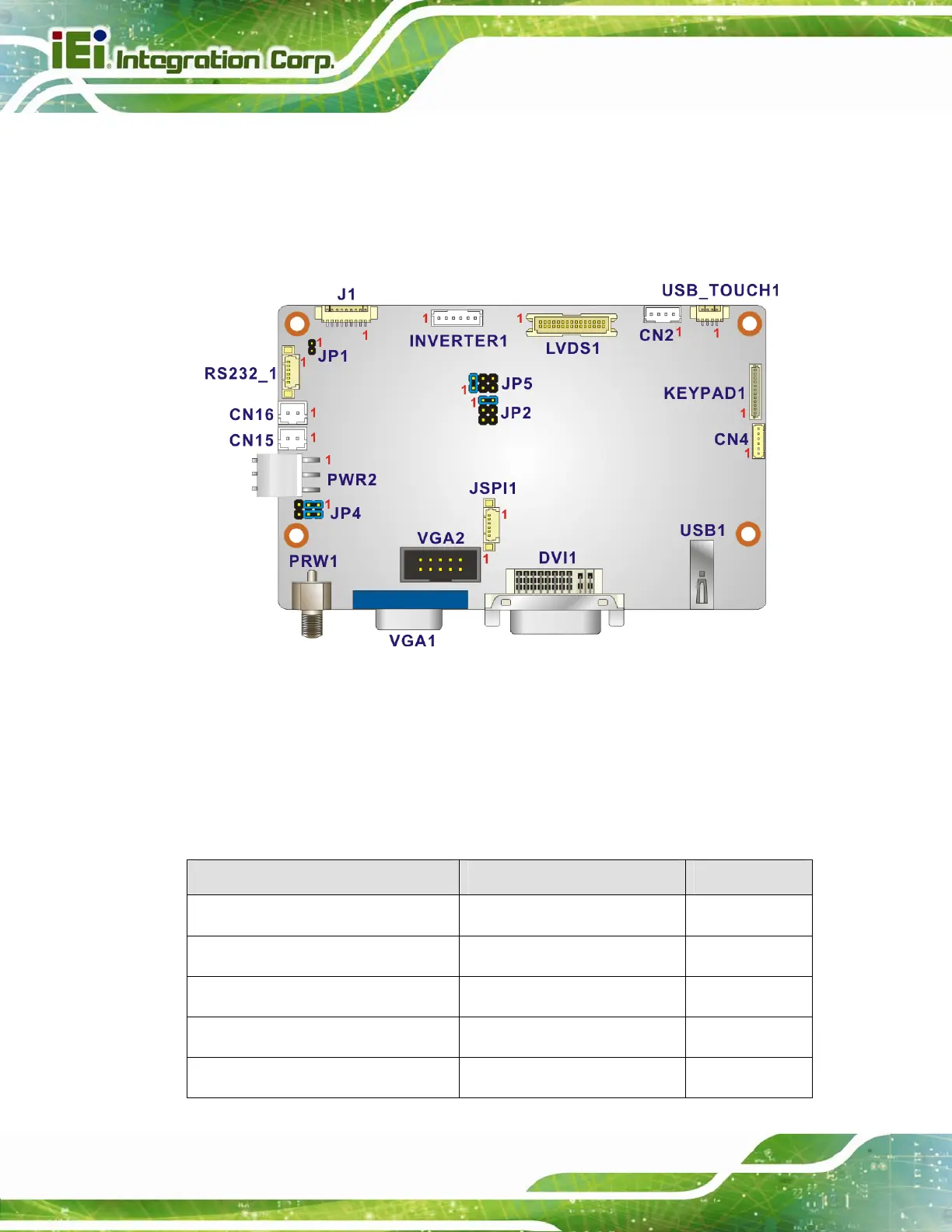
6.3 AV-60381 AD Board
The connector locations of the AV-60381 are shown in Figure 6-1. The Pin 1 locations of
the on-board connectors are also indicated in the diagrams below. The connector pinouts
for these connectors are listed in the following sections.
Figure 6-2: AV-60381 AD Board Layout Diagram
6.3.1 AV-60381 Peripheral Interface Connectors
5Table 6-11 shows a list of the peripheral interface connectors on the AV-60381 AD board.
Pinouts of the connectors that are used in the DM-F series can be found in the following
sections.
Connector Type Label
Auto dimming connector 6-pin wafer, p=1.25 mm CN4
Backlight Inverter connector 6-pin wafer, p=2.00 mm INVERTER1
COM debug port connector 2-pin wafer, p=2.00 mm CN2
LVDS connector 30-pin crimp, p=1.25 mm LVDS1
OSD keypad connector 12-pin wafer, p=1.00 mm KEYPAD1
 Loading...