17
Meaning of abbreviations in the following description
• SDTV: 480i, 575i
• HDTV: 1035i, 1080i, 480p, 720p
• SD-SDI: SDTV(480i, 575i)SDI
• HD-SDI: HDTV(1035i,1080i,720p)SDI
① INPUTSELECT switch
Use the and switches to switch the input chan-
nels A/B/C of each module. The switching depends
on the number of inputs with each module.
As the SYNC INT/EXT setting is memorized by
channel (A, B, C, YPbPr/RGB-A or YPbPr/RGB-B)
for analog inputs, it is switched automatically to-
gether with the channel switching.
As the ASPECT 4:3/16:9 setting is memorized by
channel (A, B, C, YPbPr/RGB-A, YPbPr/RGB-B,
SDI-A or SDI-B) irrespective of the format, it is
switched automatically together with the channel
switching.
② DIGITAL switch
Set to ON when selecting the MULTI-SDI, HD-SDI
or SD-SDI module.
The switching method differs as follows according
to the mounting state of the SDI module.
a) When only one SDI module is mounted.
Set the DIGITAL switch to ON.
b) When two SDI modules are mounted.
MULTI-SDI or HD-SDI can be selected only with
the DIGITAL switch. To select SD-SDI, set the 2nd
SLOT switch to ON as well.
As the ASPECT 4:3/16:9 setting is memorized by
channel irrespective of the format, it is switched
automatically together with the channel switching.
③ YPbPr/RGB switch
Set to ON when selecting the YPbPr/RGB input.
Switch between YPbPr and RGB at the MENU 1-4
item.
As the SYNC INT/EXT setting is memorized by
channel (A or B) for YPbPr/RGB, it is switched au-
tomatically together with this switch.
As the ASPECT 4:3/16:9 setting is memorized by
channel irrespective of the format, it is switched
automatically together with the channel switching.
④ 2nd SLOT switch
When there are two SDI modules (e.g. DKM-511 +
DK-801A) mounted or two decoder modules
(e.g. DE-801 + DE-811) mounted, switch to the sec-
ond slot using this switch.
a) For SDI module
The DK-801A is assigned to the 2nd SLOT.
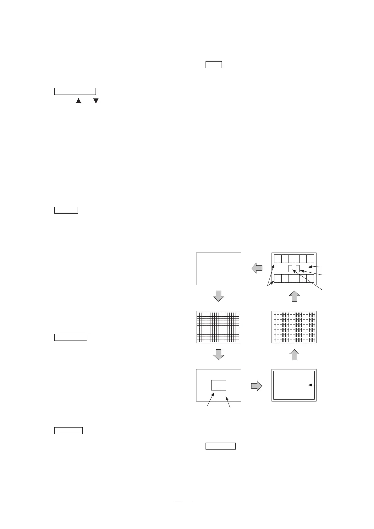
NormalScreen
Crosshatch
100%Window 50%Full-white
Character
Staircasewavewithpluge
10〜100%
staircasewave
100% 0%
SETUP
0%
SETUP
50%
+2%
-2%
Fig. 4-3-3. TEST Signal
⑥
EXT SYNC LED
The LED lights up when SYNC INT/EXT is
switched to EXT.
b) For decoder module
The DE-811 is assigned to the 2nd SLOT.
⑤
TEST switch
Turn ON to switch to the internal TEST signal.
The following standard TEST signal formats are pro-
vided.
Switch the format at the MENU 1-5 item.
480i (525i) /59.94
575i (625i) /50
480p/59.94 * Only when supported by the monitor
1035i/60
1080i/60
1080i/50
1080p/24sF (1080i/48)
*Only when supported by the monitor
720p/60
720p/50 * Only when supported by the monitor
* The description in parentheses appears on the
MENU.
As the ASPECT 4:3/16:9 setting is memorized irre-
spective of the format, it is switched automatically
when the new setting is done.
Every time the switch is pressed, the output will
cycle over the following five types of signals.




 To Next Page