18
⑦ MONO (SPLIT) Switch
Set the MONO switch to ON when the color signal
is to be viewed in the black/white state.
When the MONO switch is ON with the NTSC com-
posite signal (DE-801/811 module) selected, the lu-
minance (Y) signal is usually filtered with a comb
or trap filter. If the FORCED switch in the drawer
panel is turned on, the wide-band MONO mode
with unfiltered flat frequency characteristic is
called up.
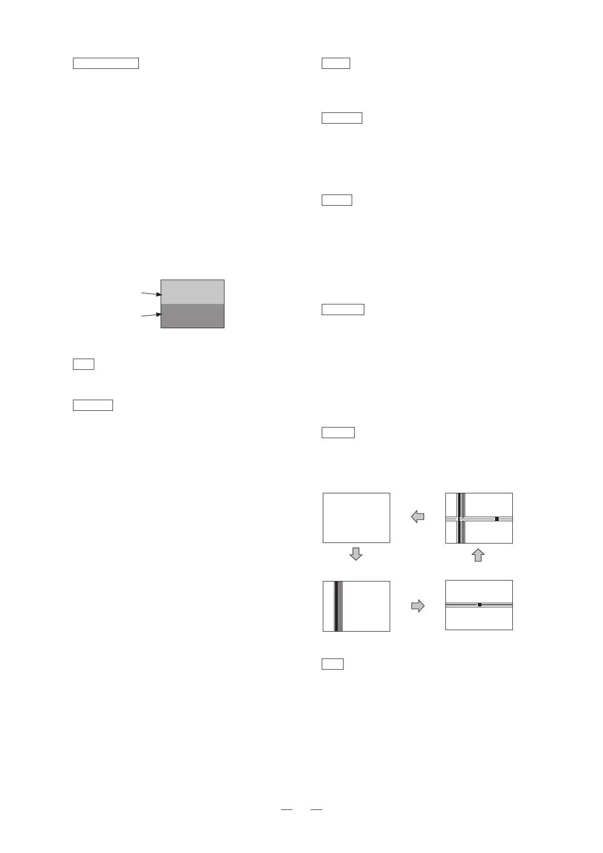
COLOR/MONO SPLIT
When the MONO switch is pressed for 2 to 3 sec-
onds, the split screen (upper half of the screen is
color, while the lower half is black/white) mode will
be set. Press the switch again to get back to the
color mode.
⑧ APT switch
Turn ON the APT switch when correcting aperture.
⑨ ASPECT switch
Aspect ratio is switched between 4:3 and 16:9.
In the HDTV signal mode for 16:9 image, the 4:3
area image is displayed with enlargement.
When CHANGE ASPE is set to AUTO in MENU 2-
4, the aspect settings are memorized in the follow-
ing seven input channels and there is no need to
repeat the setting every time the input channel or
signal format is changed. The setting is switched
automatically together with the channel switching.
In the case of the Multi-format SDI input, the as-
pect ratio data is memorized in each input signal
(HD-SDI or SD-SDI) respectively. When HD-SDI
(16:9) signal input at the channel A is replaced by
SD-SDI signal, for example, the aspect ratio is au-
tomatically switched to the one previously set for
that SD-SDI signal. To fix the aspect ratio setting,
set CHANGE ASPE to MANUAL.
<Channels for Memory>
• VBS input ch A / B / C
• 2nd VBS input: ch A / B / C
• YPbPr/RGB inputs: ch/A/B
• Multi SDI inputs: ch/A/B
(memorized in SD/HD-SDI respectively)
• 2nd SDI inputs: ch/A/B
Example:By setting the channel A to 4:3 and the
channel B to 16:9 once, the ASPECT will
be switched automatically each time the
channel A/B is switched.
NormalScreen
H&V.DELAY
V.DELAY
H.DELAY
Fig. 4-3-5. DELAY Mode
Colorpicture
B/Wpicture
Fig. 4-3-4. COLOR/MONO SPLIT ON State
⑩
SCAN switch
Use the SCAN switch to switch between normal
scan and under-scan.
⑪ SCREEN switch
When displaying the individual R, G, B screen col-
ors, turn ON the respective SCREEN switches for
R, G and B. When the switches are all ON, the
LEDs are all OFF.
⑫ COMB switch
(Only when DE-801/811 is mounted)
To operate the comb filter circuit, turn ON the
COMB switch. To operate the trap filter circuit,
turn it off.
Operation is enabled during the analog/digital
(4Fsc) NTSC composite signal input.
⑬ MARKER switch
Turn ON the MARKER switch to display the vari-
ous markers.
The markers are selected from the 4-5. Types of
Markers with the rotary encoder in the front-panel
drawer.
This switch also functions as the 4:3/13:9/14:9
shadow switch.
⑭ DELAY switch
By pressing this switch, the horizontal/vertical
blanking can be monitored. Every time the switch
is pressed, the mode cycles as follows.
⑮ HUE manual switch and control
This control serves as a MANUAL/PRESET data
selection switch as well as a manual data variable
control.
The control pops out and is switched to the
MANUAL state with each press (the LED lights).
By rotating the control in this state, the manual
data can be varied.
HUE operates only for the analog/digital (4Fsc)
NTSC composite signal input.




 To Next Page