page 4
OVERVIEW
3
LED INDICATORS: When high/low setpoints are
set, LED indicates below (–NG), within (OK), or
above setpoint value (+NG)
KEYPAD
ON/OFF: Press to turn ON, hold more than one
second to turn OFF
SEND: Press to send data to internal gauge
memory, press and hold for data hold
PEAK: Press to toggle Peak and Real Time
ZERO: Resets the display, tares attachments
MENU: Press to select data on Multi Display.
(see pages 32-33)
Program Menu: with gauge ON, press and
hold two seconds to enter Program Menu.
Setup Menu: with gauge OFF, press and hold,
then press ON/OFF to enter Setup Menu.
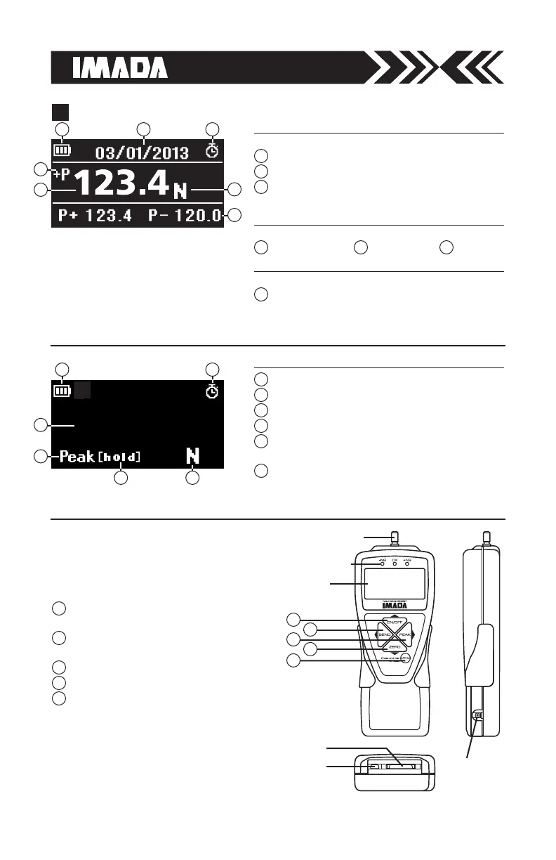
1
2
3
4
5
Battery status indicator
Auto zero icon: appears when Auto Zero is set.
Force value
Peak indicator
Peak hold: Appears when external hold signal is
active or SEND is pressed.
Units
1
2
5
6
4
3
Peak indicator Force value
4 5
Units
6
MEASURING SHAFT
KEYPAD
EL DISPLAY
USB PORT
I/O PORTS
LED INDICATORS
AC ADAPTER
PORT
2
4
1
3
5
1 2
1 2
3
4
65
3
5
4
6
7
See page 37 to switch between
Multi and Single display.
MULTI DISPLAY
Upper Section
Lower Section
Select data: Peak value, Force level, Memory
number/value, High/low setpoints (see pages 32-33).
7
Middle Section
Battery status indicator
Auto zero icon: appears when Auto Zero is set.
Select data: Date, Time, Stored memory data,
Measurements over high setpoint (see pages 32-33).
1
2
3
SINGLE DISPLAY
 Loading...