42
43
44
32
8.5 CHOOSE THE INSULATION OF THE
REFRIGERANT PIPE.
- Select the appropriate insulations according to the size of the gas
and liquid pipes.
- e standard conditions are with a temperature of 30° C and a
humidity of 85%. If the units are installed in extreme climatic
conditions, select the insulation from the table in gure 42.
ATTENTION:
- apply the insulation in such a way
that it does not expand and use the
adhesives on the relative connection part to
keep out moisture.
- Wrap the refrigerant pipe in insulating tape
if it is exposed to external sunlight.
- Install the refrigerant pipe making sure that
the insulation is not thinner on bends or in
the fairlead.
Type of pipe Pipe diameter (mm)
Insulation thickness
Notes
Normal
(Below 30°C, 85 %)
High humidity
(Over 30°C, 85 %)
EPDM, NBR
Liquid ø 6.35 ~ ø19.05 9 9
e m
aterial must be
a
ble to withstand heat
beyond 120°C
Gas ø15.88 19 25
Item Unit Standard Notes
Density g/cm 0.048 ~ 0.096
KSM 3014-01Path dimensions changed by heat % -5 or less
Water absorption rate g/cm 0.005 or less
er
mal conductivity kc
al/m·h·˚C 0.032 or less KSL 9016-95
Moisture transpiration factor ng/(m
·s·Pa) 15 or less KSM 3808-03
Moisture transpiration degree {g/(m·24h)} 15 or less KSA 1013-01
Dispersion of formaldehyde mg/l - KS
F 3200-02
Oxygen rate % 25 or less ISO 4589-2-96
8.6 INSULATING THE REFRIGERANT PIPE.
- You must check that there are no gas leaks before completing
the entire installation process.
- Use EPDM insulation which meets the conditions described in
the table in gure 43.
- Make sure to insulate the refrigerant pipes, the joints and the
connections with class ‘o’ material.
- By insulating the piping, condensate water does not drip from
the pipes, improving the condensing unit’s capacity.
-
Check that there are no cracks in the insulation where the pipe bends.
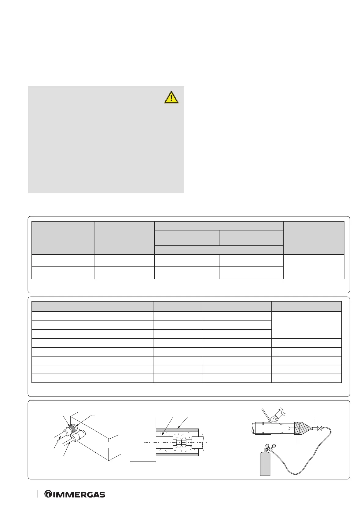
8.7 BRAZE WELDING THE PIPE.
- Make sure there is no moisture inside the pipe.
- Make sure there are no foreign bodies or impurities in the pipe.
Replacing nitrogen gas.
1. Use oxygen-free nitrogen during braze welding of the pipes, as
shown in gure 44.
2. Oxidation can form in the pipe if nitrogen gas is not used dur-
ing braze welding. is can damage the compressor and valves.
3. Adjust the ow of the replacement gas with a pressure regulator
to maintain the ow rate no lower than 0.05 m3/hour.
4. Execute braze welding of the service valve aer having protected
the valve.
Insulation
Clamp
Indoor unit
Gas side pipe
Liquid side
pipe
Indoor
unit
Insulation
Install insulation to
overlap
Overlap
Part to
braze weld
1/4" copper pipe
Pressure regulator
Stem
valve
Touch
Nitrogen gas