50
48 49
d
GWP = 675
(1)
(2)
36
- a. Charge product refrigerant in factory: See rating
plate.
- b. Amount of additional refrigerant charged on-site.
(Refer to the information below for the amount of
refrigerant charge).
- c. Total refrigerant recharge.
- d. Refrigerant cylinder and charge manifold.
ATTENTION:
- inform the user if the system contains
5 tCO
2
e or more of uorinated green-
house gases. In this case, a leak test must be
carried out once every 12 months, in com-
pliance with regulation No. 517/2014. is
job must be carried out by professionally
qualied technical personnel only. In the
situation considered above, the installer
(or authorised person in charge of the nal
control) must dra a maintenance booklet
containing all of the information prescribed
in REGULATION (EU) No. 517/2014 OF
THE EUROPEAN PARLIAMENT AND OF
THE COUNCIL of 16 April 2014 on uori-
nated greenhouse gases.
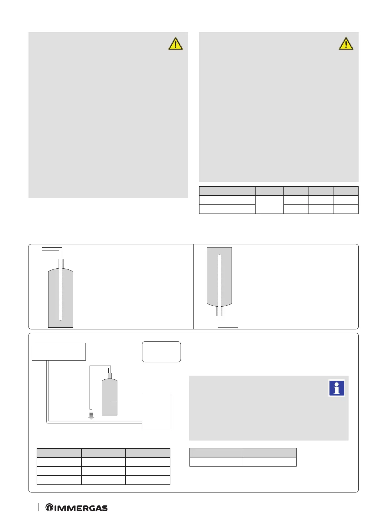
- Before charging, check whether or not there is a siphon is
attached on refrigerant cylinder and position the cylinder
accordingly (see gures 48-49).
Fill in the following form with indelible ink on the refrigerant charge label
supplied with this product and on this manual.
- 1 = refrigerant charge of product in factory.
- 2 = amount of additional refrigerant charged on-site.
- 1+2 = total refrigerant charge
Type of refrigerant GWP value
R-32 675
GWP: Global Warning Potential
Calculation tCO
2
e: kg x GWP / 1000
Unit Kg tCO
2
e
(1), a
(2), b
(1) + (2), c
ATTENTION:
- the compiled label must be applied
near the product load door (for ex-
ample on the inner side of the casing of the
stop valve).
- Make sure that the total refrigerant charge
does not exceed (A), the maximum refrig-
erant charge, which is calculated with the
following formula: Maximum refrigerant
charge (A) = refrigerant charge (B) + max-
imum additional refrigerant charge due to
extension of the piping (C).
- e following table summarises the refrig-
erant charge limits for each product.
Model Unit A B C
AUDAX P
RO 4-6 V2
g
1500 1200 300
AUDAX P
RO 9 V2 1800 1400 400
Indoor unit
Outdoor unit
Charging using a cylinder with attached
siphon
Charge the refrigerant keeping the cylinder
upright
Charging with cylinder without attached
siphon
Charge the liquid refrigerant with the cylinder
upside down