Chapter 4 Software index
4-26
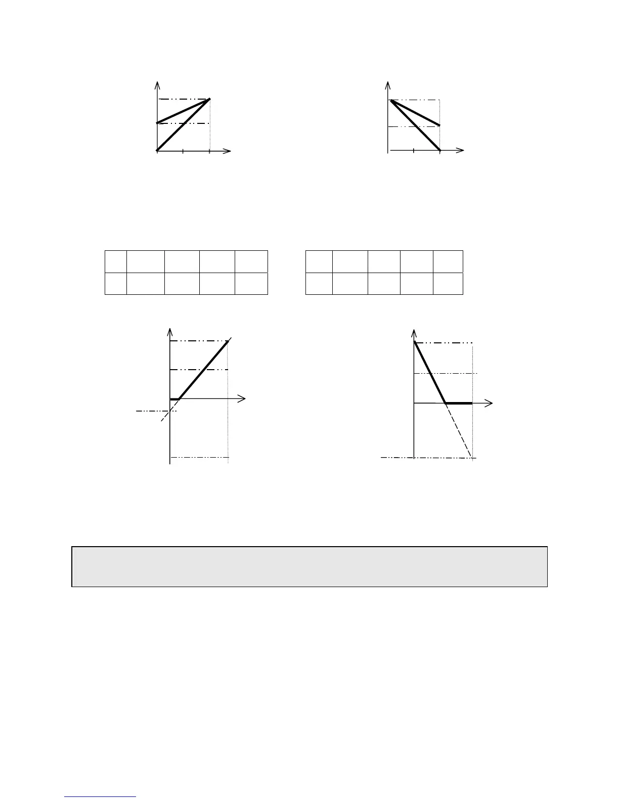
Fig (3) example settings below: Fig (4) example settings below:
b62 b63 b64 b65
b62 b63 b64 b65
E 100% 020% 001 000
F 100% 100% 001 001
b64 AIN Bias: 000: Positive 001: Negative
b65 AIN Signal Slope direction. 000: Positive 001: Negative
b66 AIN signal scan time confirmation. (mSec × 8): 001 – 100
Refer to b62/b63 description
The inverter reads A/D average value every b66 x 8mS. The user can set scan interval time according
to noise in the operation environment. Increase value of b66 if electromagnetic noise is a problem but
note that the inverter response time will be slower.
Upper frequency
limit (A02=60.0)
Upper frequency
limit (A02=60.0)
60Hz
30Hz
Bias
0Hz
0V
(4mA)
A
B
5V
10V
(20mA)
100%
050%
000%
Fig (1)
Upper frequency
limit (A02=60.0)
Hz
Ref
60Hz
30Hz
0Hz
0V
(4mA)
C
D
5V
10V
(20mA)
Bias
100%
050%
000%
Fi