Chapter 5 Trouble shooting and maintenance
5-9
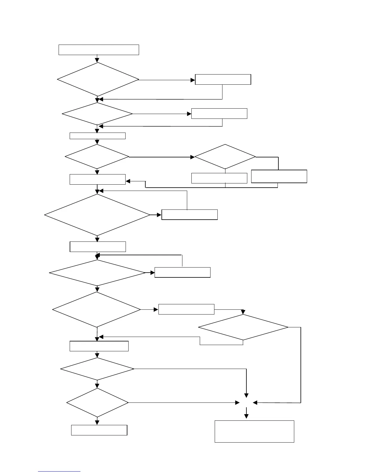
Troubleshooting for OC, OL error displays
Is the main circuit
I.G.B.T. OK?
Any abnormal
indications?
Replace the current sensing
circuit
iDrive displays OC or OL errors
Apply the powe
Input operation commands
Replace I.G.B.T Module
Replace faulty circuit boards
Is the current
detector OK?
Replace the control board
Replace the control board
O
YES
YES
Input frequency command.
requency
of the operating unit
displayed?
Are there voltage
outputs at T1, T2, and
T3 output terminals?
Connect motor and test run.
values displayed?
Are output
currents of each
hase even?
The inverter’s output is OK
Replace the control board
Replace the control board
Is the control board
working well after
Perform detailed checks
The inverter faults
YES
YES
YES
YES
o
Does output frequency
continue to be
displayed or display
shows SP1?
o
Yes
Inverter faulty.
Contact your iDrive supplier