6-6 SECTION 6. GENERAL REFERENCE99903514:TELESCOPIC CRANE:
CRANE CAPACITY & STABILITY
The crane capacity is defined on the capacity
placard, a decal which is mounted near the
operator’s station on the crane. The capacity
placard information is based on the crane, winch,
cable and stabilizers being structurally sound and
a stability factor of 85% of the balance point.. All
load ratings are dependent upon compliance with
the following:
1. Stabilizers fully extended and stabilizer pads
firmly contacted with a solid, stable and level
surface.
2. The crane has been installed on a factory
approved vehicle and in a factory approved
fashion.
3. The carrier vehicle’s tires are properly inflated.
4. Any load handling devices have been added to
the weight being lifted.
5. Extreme wind velocities are not present.
6. The crane is operated in a smooth and con-
trolled manner.
7. Any required counterweights have been added.
In addition, each stated capacity is directly related
to the radius of a given operation. The radius is
measured from the load line to the centerline of
rotation on the horizontal plane.
WARNING
THE MINIMUM CURB WEIGHTS SHOWN IN THE
SPECIFICATIONS IN VOLUME 2, PARTS AND
SPECIFICATIONS DO NOT ENSURE THE UNIT WILL
BE STABLE. ACTUAL STABILITY RATINGS WILL BE
OBTAINED FROM THE INITIAL START-UP AND
TESTING PROCEDURES.
Required axle weights for the crane mounted on a
chassis meeting the minimum chassis require-
ments are shown in Volume 2, Specifications.
CAUTION
STABILITY FACTORS DO NOT TAKE THE FRONT AXLE
LOAD RATING INTO CONSIDERATION. DUE TO THE
CAPACITY RATING OF THE FRONT AXLE, THE
LOADING 75° EITHER SIDE OF THE CENTERLINE
OVER THE CAB MUST BE SEVERELY RESTRICTED.
20120104
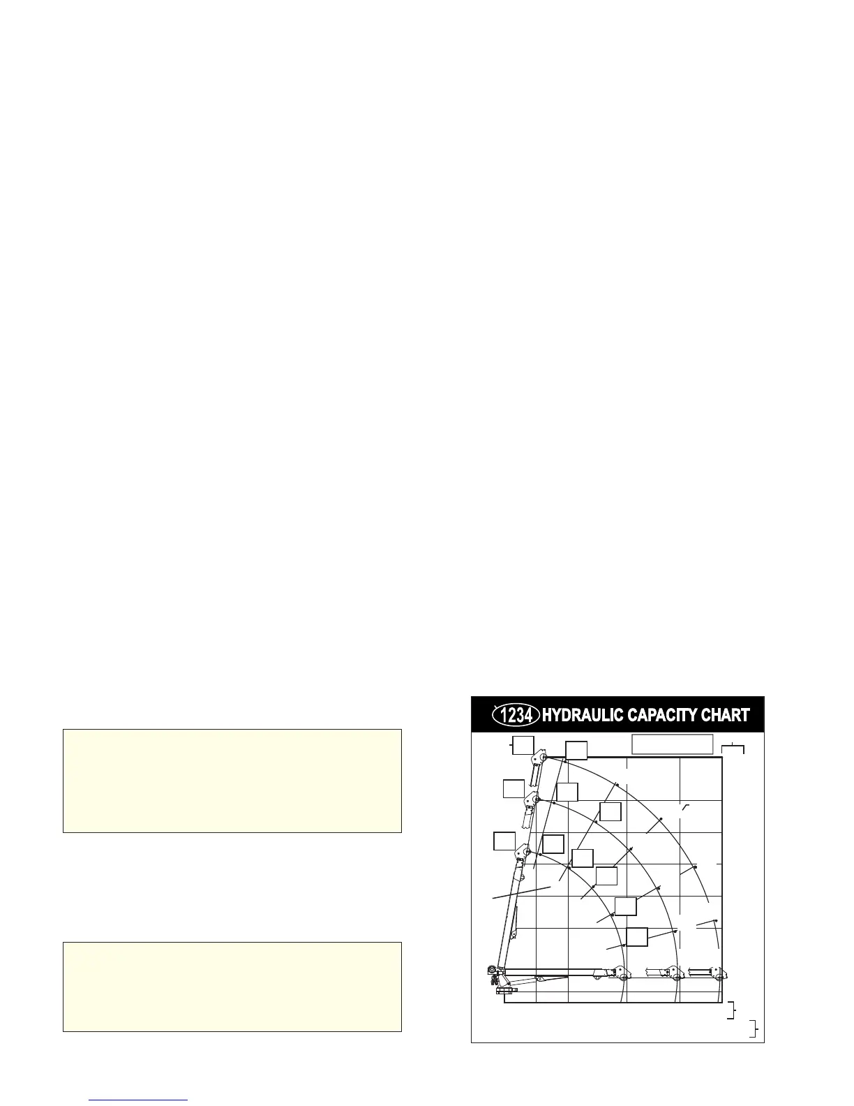
UNDERSTANDING THE CAPACITY
PLACARD
The following information is defined on Figure F-1,
a sample capacity placard. This placard is an
example only! The capacity information is not
intended for use on any particular crane.
1. Crane model number.
2. This note is a reminder that it is necessary to
add the weight of load handling devices to the
weight of the object being lifted in order to derive
the actual total load being lifted.
3. Capacities which are “boxed” indicate crane
capacities which exceed 1-part line capabilities.
To lift these maximum loads in these ranges, it is
necessary to use 2-part line.
4. Capacities which are not “boxed” are within 1-
part line limits.
5. Distances from centerline of rotation to various
lifting points.
6. Lifting height reference dimensions from base
of crane. The mounting height of the crane must
be added to these dimensions to determine
accurate vertical heights.
7. Crane boom angle reference figures. The
angle of the lower boom as shown by the angle
indicator on the lower boom should be compared
to these figures.
FIGURE F-1: SAMPLE CAPACITY PLACARD
6700
(3039)
7500
(3402)
7500
(3402)
7500
(3402)
80
75
60
45
30
15
0
0 3’-0"
(91.4 cm)
6’-0"
(1.83 m)
11’-6"
(3.51 m)
16’-6"
(5.03 m)
20’-6"
(6.25 m)
0
1’-4"
(40.6 cm)
6’-0"
(1.83 m)
9’-0"
(2.74 m)
12’-0"
(3.66 m)
15’-0"
(4.57 m)
18’-0"
(5.49 m)
22’-1"
(6.74 m)
6550
(2971)
5350
(2427)
6180
(2803)
4330
(1964)
3500
(1588)
2730
(1238)
3420
(1551)
4980
(2259)
4370
(1982)
3850
(1746)
3320
(1506)
2200
(998)
2570
(1166)
1740
(789)
2030
(921)
2950
(1338)
2340
(1061)
REACH IN FEET (METERS)
CAPACITY IN POUNDS (KILOGRAMS)
Weight of load handling devices are part of the load
lifted and must be deducted from the capacity.
2
1
Maximum 1-part line capacity is
3800 lb (1725 kg). For greater
loads, use 2-part line.
3
4
5
6
7