99903514:TELESCOPIC CRANE: 4-13
SECTION 4: INSTALLATION
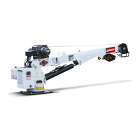
4.12 MODELS 5525, 6025, AND 6625
CRANE INSTALLATION
5525 MINIMUM CHASSIS SPECIFICA-
TIONS
BODY STYLE Conventional
Cab
WHEELBASE 154”
CAB TO AXLE 84”
FRAME SECTION MODULUS 12 in³
RBM 600,000 in-lb
FRONT AXLE RATING 7000 lb
REAR AXLE RATING 17,500 lb
GROSS VEHICLE RATING 24,500 lb
TRANSMISSION 5-speed
6025 MINIMUM CHASSIS SPECIFICA-
TIONS
BODY STYLE Conventional
Cab
WHEELBASE 154”
CAB TO AXLE 84”
FRAME SECTION MODULUS 14.5 in³
RBM 720,000 in-lb
FRONT AXLE RATING 9000 lb
REAR AXLE RATING 17,000 lb
GROSS VEHICLE RATING 26,000 lb
TRANSMISSION 5-speed
6625 MINIMUM CHASSIS SPECIFICA-
TIONS
BODY STYLE Conventional
Cab
WHEELBASE 154”
CAB TO AXLE 84”
FRAME SECTION MODULUS 16 in³
RBM 800,000 in-lb
FRONT AXLE RATING 9000 lb
REAR AXLE RATING 17,000 lb
GROSS VEHICLE RATING 26,000 lb
TRANSMISSION 5-speed
CRANE INSTALLATION
In addition to meeting Minimum Chassis
Specifications, there must be sufficient room
for mounting the crane and the platform must
be strong enough to support the crane and
rated load. Install the crane only on an IMT
designed and approved truck body. The body
must be designed to sustain the forces
imposed by the crane when lifting the full rated
load. In addition, an IMT designed body is
designed to take full advantage of the standard
reservoir placement. This reservoir is in-
stalled in the cargo area of the body. Before
attempting to install the crane, the body must
be installed.
To install the crane:
1. Use a lifting device capable of lifting the
weight of the crane. See Specifications Sec-
tion for crane weight. Attach fabric slings to
the crane lower boom, centered approximately
18 inches from the mast hinge. Make certain
the crane is well balanced on the slings by
slowly lifting approximately 6" off the ground.
Lift the crane, apply a bead of waterproof
compound, such as silicon based caulk, to the
bottom of the base. Move the chassis under
the crane and lower the crane into the desired
position.
2. Install the 1-8x3.0” mounting cap screws
and 1" washers to secure the crane base to
the truck body (see Crane Installation draw-
ing). Torque the cap screws to 680 ft-lbs (94
kg-m).
CAUTION
THE 3.0” BOLTS SUPPLIED ARE FOR
USE ON BODIES WITH A CRANE BOX
TOP PLATE THICKNESS OF 7/8-1”
ONLY. DETERMINE THE CRANE BOX
TOP PLATE THICKNESS PRIOR TO
MOUNTING. IF DIFFERENT LENGTH
BOLTS ARE REQUIRED, THEY MUST
BE 1-8, GRADE 8 (MINIMUM) OF THE
PROPER LENGTH. FAILURE TO USE
PROPER LENGTH BOLTS MAY CAUSE
THE BOLTS UNDER THE WORM HOUS-
ING TO BOTTOM OUT BEFORE
TORQUEING. INSURE A MINIMUM OF 1-1/
2” THREAD ENGAGEMENT.
20030115