99903514: TELESCOPIC CRANE: 1-9 SECTION 1: OPERATION
1-7: CRANE CAPACITY AND LOAD LIM-
ITS
The IMT crane is designed to lift specific loads.
These loads are defined on the capacity placard
mounted near the operator’s station and on the
crane. Exceeding the limits presented on the
capacity placard will create severe safety
hazards and will shorten the life ot the crane.
The operator and other concerned person-
nel must know the load capacity of the crane
and the weight of the load being lifted!
WARNING
NEVER EXCEED THE CRANE’S RATED LOAD
CAPACITIES. DOING SO WILL CAUSE
STRUCTURAL DAMAGE AND DAMAGE TO
WINCHES AND CABLES WHICH CAN LEAD TO
SERIOUS INJURIES OR DEATH.
NOTE
LOAD LIMIT INFORMATION ON THE CAPACITY
PLACARD IS FORMULATED ON 85% OF TIPPING.
“TIPPING REFERS TO THE CRANE ACTUALLY
TIPPING WITH ITS OPPOSITE OUTRIGGER AND
TIRES HAVING BROKEN CONTACT WITH THE
SURFACE.
Prior to lifting a load:
1. Determine the weight of the load.
2. Determine the weight of any load handling
devices.
3. Add the weight of the load and the weight of
the load handling devices. The sum will be the
total weight of the load being lifted.
4. Determine the distance from the centerline of
crane rotation to the centerline of the load being
lifted.
5. Determine the distance from the centerline of
crane rotation to the centerline of where the load
is to be moved to.
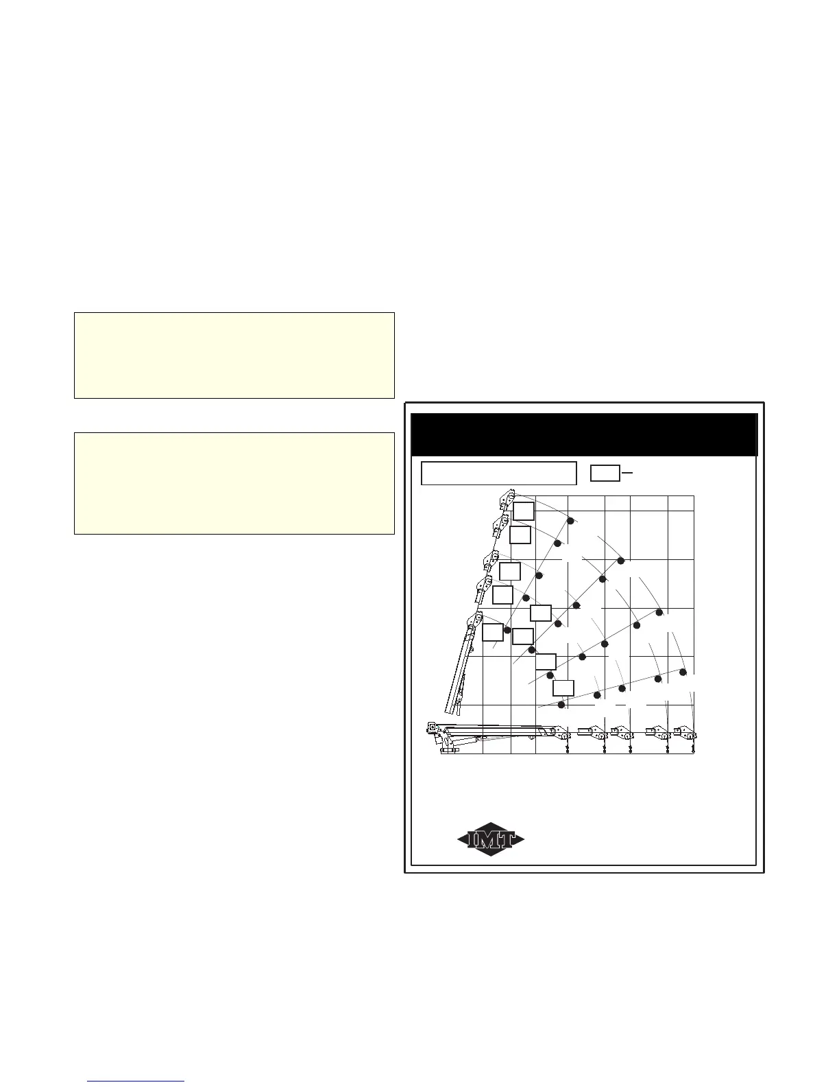
Maximum 1 part line is 4675 lb (2121 kg).
Values in the box denote
the use of 2 part line.
See reduced capacity placard for additional
information if applicable.
XXXX lb
XXXX kg
REACH IN FEET
CAPACITY IN POUNDS
(METERS)
(KILOGRAMS)
Weight of load handling devices
are part of the load lifted and must
be deducted from the capacity.
IOWA MOLD TOOLING CO., INC.
BOX 189, GARNER, IA 50438-0189
TEL: 641-923-3711 FAX: 641-923-2424
HYDRAULIC CAPACITY CHART
CENTERLINE
25'
20'
15'
10'
26'-7"
2'-2"
0
6'-6"
(1.98m)
3'-7"
(1.09m)
9'
(2.74m)
15
45
60
75
18'-10"
(5.74m)
12'-4"
(3.75m)
16'-2"
(4.92m)
22'-8"
(6.90m)
25'-4"
(7.72m)
5'
(4.57m)
(0.66m)
(1.52m)
(3.04m)
(6.09m)
(7.62m)
(8.10m)
2870
(1302)
5000
(2268)
5430
(2463)
7170
(3252)
8310
(3769)
5280
(2395)
8925
(4048)
5700
(2585)
4180
(1896)
2850
(1293)
2340
(1061)
1900
(862)
1650
(748)
6040
(2740)
7080
(3211)
3290
(1492)
3700
(1678)
4460
(2023)
2540
(1152)
3490
(1583)
2990
(1356)
2440
(1107)
2150
(975)
4520
(2050)
3230
(1465)
2660
(1207)
2150
(975)
1900
(862)
3610
(1637)
4060
(1842)
30
Figure A-10: Sample Telescopic Crane
Hydraulic Capacity Chart
6. The actual distance used should be figured
as the larger of items 4 and 5 above.
7. Determine at what angle the crane will be
operated (for example 30°, 45°, etc.) by refer-
encing the angle indicator on the lower boom.
8. Make certain that 2-part line is used for any lift
which requires 2-part line. (Note: The two-part
line weight is noted in a box on the capacity
chart.)
For more information on crane stability con-
cepts and the hydraulic capacity placards, refer
to Section 6, Reference, of this manual.
20030115