99903514:TELESCOPIC CRANE: 3-13 SECTION 3: REPAIR
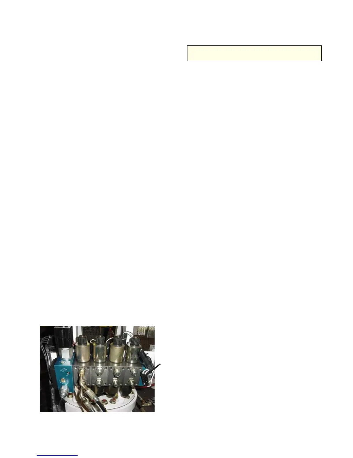
Figure C-14: Valvebank End Caps
3-13-2: VALVEBANK TROUBLESHOOT-
ING
1. Determine which functions are not working,
and locate the valves that control these
functions.
2. Check valve functions including:
Questionable Operation of Coil - Remove
the coil at the top of the valve, then remove
the coil at the bottom of the valve.
Foreign Material - Foreign material can
interfere with the electromagnetic field. Thie
could include any corrosion on the inside of
the coil and the stem the coil rests on.
Check indicator lights on valve driver.
Check voltage to coil under load. Is there
sufficient voltage to operate the coil?
Check if solenoid is magnetized.
Switch the hose from a know working
function to a non-working function. If valve
begins to work, failure is not due to the valve
bank.
3. Clean coils, stem, and replace coil.
3-13-3: SINGLE VALVE REPLACEMENT
Prior to replacing a single valve or a complete
valvebank, make sure you have a clean, flat
working surface.
To replace a single valve, loosen the bolts at
each end of the valvebank and remove the pins
which hold the valve in place. Slide out the
valve which has failed, and slide in the new
valve. Re-torque bolts to 80 in-lb.
NOTE
VALVEBANK TORQUE IS MEASURED IN
INCH-POUNDS, NOT FOOT-POUNDS!
When ordering replacement valve sections,
check the end caps on the valvebank. There
are different replacement valves for valvebanks
with blue or silver end caps. Contact IMT
technical support for more information.
3-13-4: VALVEBANK REMOVAL AND
REPLACEMENT
To remove and replace the valvebank:
1. Identify and mark all hoses and position
points and the control valve. Remove hoses
from the valve. Cap or plug all open hydrau-
lic fittings.
2. If needed, use a sling to lift the valvebank.
Hook the sling on a hoist. Raise the hoist to
tension the sling. Remove hardware secur-
ing valve to crane base, and position valve
on a firm work support.
3. Reverse the procedure for re-assembly.
DO NOT induce any distortion in the valve
body when mounting. Use shims under
mounting pads if necessary to prevent
distortion. Torque threaded fasteners per
Torque Data Charts. Observe hose identifi-
cation when reconnecting hoses to valve.
4. Start the crane. With no load, slowly cycle
all cylinders out and in to purge air from the
system.
5. After the air has been purged, check the
reservoir oil level. Top off if necessary.
Blue
valve
end
caps
20030115