99903514:TELESCOPIC CRANE: 3-11 SECTION 3: REPAIR
4. Replace the bearing if needed. Otherwise,
lightly grease and reassemble.
To replace bearings:
1. Start the bearing in its respective hole by
rotating the bearing while applying pressure.
Align the grease zerk hole with the bearing
hole (if applicable). Once started, drive the
bearing to its full counterbored depth by
tapping with a rubber mallet. Use a mallet
with a head larger than the bearing so the
bearing isn’t damaged.
2. If the bearing is loose, tighten the bearing by
centerpunching the bore diameter in about
50 places around the 2” deep bored area.
3. After installing bearings , and before assem-
bling the machine, insert the pins through
both bearings in each end of the lift cylin-
ders, and through the boom pivot bearings,
to ensure alignment and fit are correct. Pins
should slide freely through the leading hole
and start in the opposite hole. If the pin
binds, do not force it. Remove the pin, clean
the hole, and reinsert.
Inspect bushings and bearings as needed, and
replace any damaged or worn bushings. Lubri-
cate with EP grease upon replacement.
3-13: VALVEBANK
3-13-1: VALVEBANK COMPONENTS
This section describes the operating character-
istics of the main control valvebank used tele-
scopic cranes and provides troubleshooting
information.
ELECTRICAL-AMP DRIVER
POWER LED
The Power LED illuminates red while power is
being applied to the valve amplifier. If the LED is
not illuminated, no power is being applied to the
valve amplifier.
If the Power LED does not function as de-
scribed, inspect input wiring and repair or
replace as necessary. When input power is
applied, the LED should illuminate.
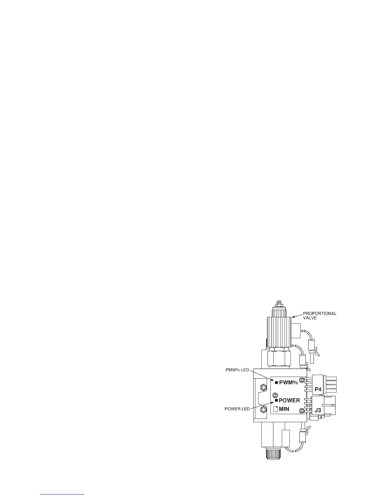
Figure C-12: Valve Functions
PMW% LED
The PMW% LED indicates the condition of the
output current flowing to the proportional valve.
The LED will change colors from red to yellow
to green. The change of colors indicates the
variance of current flowing to the proportional
valve. Red indicates minimum current and
green indicates maximum current. This repre-
sents the flow condition going from low flow
(red) to maximum flow (green), thus varying the
speed of crane functions.
If the LED stays red when the speed control
trigger is activated, a dead short is present in
the circuit. This could be the result of a wiring
problem, shorted out proportional coil, etc.
Inspect the wiring and replace the proportional
coil if required.
MIN POTENTIOMETER
The MIN adjustment potentiometer is used to
set the minimum amount of movement of an
individual function at the valvebank when the
corresponding function switch at the handset is
depressed. To adjust, set engine at high speed
control setting. Depress the “Rotation” function
switch at the handset. Adjust the MIN potenti-
ometer at the AMP driver card clockwise until
crane begins to rotate or counterclockwise until
motion begins to stop. No other electrical
adjustments are required to properly operate the
crane.
20030115