6-14 SECTION 6. GENERAL REFERENCE99903514:TELESCOPIC CRANE: 20120104
Before a bearing is removed from a crane for
inspection, one of the following conditions should be
evident:
1. Metal particles present in the bearing
lubricant.
2. Increased drive power required to rotate the
crane.
3. Noise emitting from the bearing during crane
rotation.
4. Rough crane rotation.
5. Uneven or excessive wear between the pinion
gear and turntable gear.
TURNTABLE BEARING INSPECTION FOR REPLACEMENT
If none of the above conditions exists, the bearing is
functioning properly and need not be replaced. But, if
one or more of the above conditions exists, inspection
may be required. Limits are measured in “TILT”
which is dependent on the internal clearances of the
bearing. TILT is the most practical determination of a
bearings internal clearance once mounted on a crane.
Periodic readings indicating a steady increase in TILT
may be an indicator of bearing wear. Note that a
bearing found to have no raceway cracks or other
structural irregularities should be reassembled and
returned to service.
NOTE
THE FIGURES LISTED IN
THIS CHART ARE
SERVICE GUIDELINES
AND DO NOT, IN
THEMSELVES, REQUIRE
THAT THE BEARING BE
INSPECTED.
IF THERE IS REASON
TO SUSPECT AN
EXCESS OF BEARING
WEAR AND THE
MEASURED TILT
DIMENSION EXCEEDS
THE DIMENSION
LISTED, REMOVE THE
BEARING FOR
INSPECTION.
IMT
CRANE,
LOADER
OR
TIREHAND
MODEL
BALL DIA.
(REF)
TILT DIM.
(A
1
-A
2
)
.060”
(1.524mm)
.070”
(1.778mm)
.075”
(1.905mm)
.090”
(2.286mm)
.875”
(22mm)
1.00”
(25mm)
1.18”-1.25”
(30-32mm)
1.75”
(44mm)
1007
1014
1014A
1015
2015/2020
2109
3000
3816/3820
3016/3020
421/425
4300
5016/5020
6016/6020
TH7 BODY ROT’N
TH1449 BODY ROT’N
TH15B CLAMP
TH2551B CLAMP
TH2557A CLAMP
5200
5200R
5217
5800
7020
7025
7200
7415
9000
TH10 BODY ROT’N
TH14 BODY ROT’N
16000
32018
32027
32030
T30
T40
9800
12916
13031
13034
14000
15000
18000
20017
8000L
H1200
H1200RR
T50
TH2551B BODY ROT’N
TH2557B BODY ROT’N
TH2557A BODY ROT’N
COMPARISON CHART - MODEL TO MEASURED TILT DIMENSION
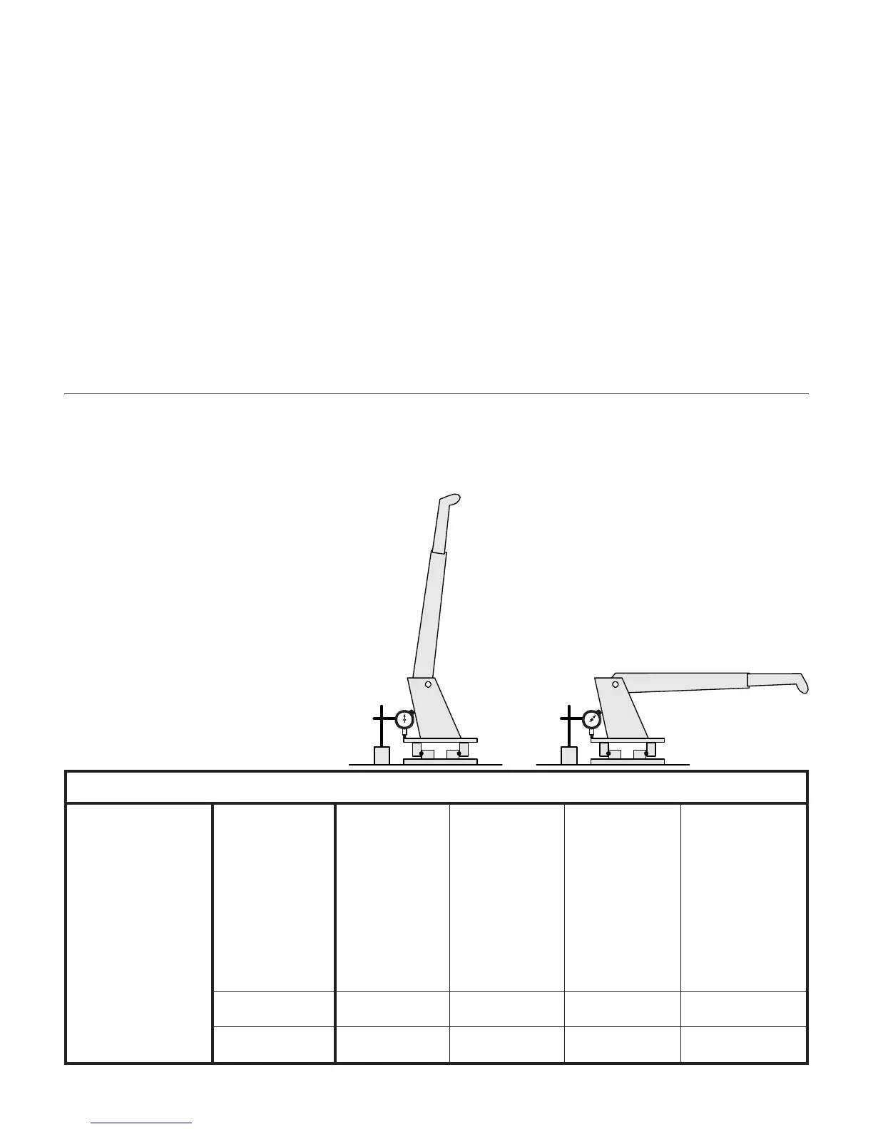
TEST PROCEDURE
1. Place crane in vertical position.
2. Set a dial indicator at 0 on the pinion cover plate at
back side of mast.
3. Lower crane to the horizontal position.
4. Check and record the dial indicator change. It
should not exceed the tilt measurement noted in
the chart below.
5. Return the crane to the vertical position. The dial
indicator should return to 0.
Set up dial indicator
to 0" on pinion cover
at back side of mast.
Lower crane to
horizontal position.
Read dial indicator.