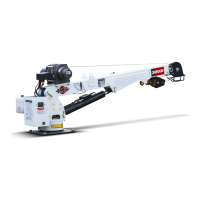
6-7 SECTION 6. GENERAL REFERENCE99903514:TELESCOPIC CRANE: 20120104
STABILITY TEST
Every IMT factory-installed crane includes a
completed stability chart. Any installer other than
IMT also has the responsibility to complete a
stability chart. Cranes are tested for stability to
85% of “tipping”, where the crane load is balanced
with the truck, and any additional load would result
in tipping. The Stability Test is per SAE J765a.
Figures entered on the stability chart are for a
specific truck and crane combination. If the crane
or vehicle are modified or replaced with another, it
is necessary to recalculate stability. By referring
to the stability chart for your crane/chassis combi-
nation, it is possible to determine the loads per-
mitted in the derated load range of your crane.
CAUTION
THE PERCENTAGES GIVEN IN THE GRAY AREA
OF THE STABILITY CHART ARE BASED ON
ACTUAL VEHICLE STABILITY AND DO NOT TAKE
FRONT AXLE RATING INTO CONSIDERATION. DUE
TO THE CAPACITY RATING OF THE FRONT AXLE,
THE LOADING 75° TO EITHER SIDE OF THE
CENTERLINE OVER THE CAB MUST BE
SEVERELY RESTRICTED.
Determine the stability of your truck and crane
combination per the following procedure:
1) Use Figure F-2: Stability Chart - Crane
Mounted Behind Cab for cranes mounted directly
behind the chassis cab, and use Figure F-3:
Stability Chart -Rear Mounted Crane for cranes
mounted at the rear of the chassis.
2) On the appropriate figure, fill out items A
through L.
3) Perform the stability test on a flat hard surface.
Ideally this surface will be concrete, but asphalt or
hard-packed gravel are acceptable. Only autho-
rized testing personnel may be in or near the test
area. Per SAE J765a, the area must be within 1%
of level.
4) Position and lower the stabilizers until the
weight of the crane has been removed from the
truck springs.
5) Extend the crane to full horizontal position,
centered over the rear of the truck.
6) From the capacity placard, determine the rated
load at the maximum horizontal reach. Place a
1 30 7 150
2 60 8 120
390990
4 120 10 60
5 150 11 30
6 180 12 0
CLOCK
POS.
DEGREES
(º)
CLOCK
POS.
DEGREES
(º)
weight equal to 118% of that rated load at the
maximum horizontal reach (L). Keep the load
close to the ground to avoid excessive tipping.
L = ft.
7) Slowly start rotating the load counterclockwise.
Through every 5° increment, check whether all
vehicle tires remain in contact with the test sur-
face.
NOTE: To make it easier to visualize degrees,
compare the rotation to numbered positions on a
clock face. As a point of reference, the rear
center of the truck is the 0° (12 o’clock) position,
and the front center is the 180° (6 o’clock) posi-
tion.
8) If at any point through the rotation cycle, any
one of the vehicle tires starts to break contact with
the test surface, stop the rotation and note the
position of the crane (X°). This is the balance
point which determines 85% of tipping for the
rated load.
X° =
9) After the balance point has been reached,
retract the extension boom until all tires are in full
contact with the test surface again.
10) Continue rotating the boom after stability has
been regained. Again, watch all vehicle tires for a
point of instability. If a point of instability reoccurs
(one of the vehicle tires breaks contact with the
test surface), retract the extension boom until
stability is regained.
11) Repeat this cycle through a full 180°.
12) At the end of the 180° arc, physically measure
the existing horizontal distance from the centerline
of rotation to the centerline of the load (K).
K = ft.