6-8 SECTION 6. GENERAL REFERENCE99903514:TELESCOPIC CRANE:
13) To determine the percent of full capacity in the
derated zone, divide the remaining horizontal
distance (K) by the original maximum horizontal
distance (L). Multiply this figure by 100.
K / L x 100 = %
14) Enter the derated percent of full capacity (Z%)
obtained in step 13 on the appropriate figure
Figure F-2: Stability Chart - Crane Mounted
Behind Cab or Figure F-3: Stability Chart -Rear
Mounted Crane. In the derated zone, each
individual capacity on the capacity chart must be
multiplied by the derated percent of full capacity
(Z%). The reduced capacities must maintain 85%
of tipping in the derated zone.
15) If the crane is a side mount, repeat the stabil-
ity test by rotating the crane clockwise through
180° of arc to find X
1
°, Y
1
° and Z
1
°.
X
1
° =
Y
1
° =
Z
1
° =
16) The figures obtained indicate the stability
range of the particular truck and crane combina-
tion only. If either the truck or crane is changes or
modified, the stability calculations must be re-
peated.
17) Rotate the crane at least 5 times to using the
completed figure to ensure the rating is accurate.
18) Be sure all information has been recorded on
the appropriate figure., and in the service manual.
19) Record the total length of time to test the
crane (total crane test and inspection time should
approximate 4 hours per SAE J765a (1979).
Total hours:
When applicable, this stability test conforms to
SAE J765a, ANSI B30.15 and USAS B30.5.
LIFTING IN THE DERATED ZONE
If it is absolutely necessary to perform a lift within
the derated load capacity zones (Y or Y1), pro-
ceed as follows:
1) Determine the distance from centerline of
rotation to the centerline of the load being lifted.
2) Determine the distance from centerline of
rotation to the centerline of where the load is to be
moved to.
3) The actual distance used should be figured as
the larger of items 1 and 2 above.
4) Refer to the crane’s capacity placard and
determine within which range the lift will be ac-
complished.
5) Refer to the capacity of that range and multiply
that figure by the derated capacity percentage (Z
or Z1).
6) Make certain that the weight of the load plus
any load handling devices does not exceed that
figure.
EXAMPLE
If Z% = 70% and crane capacity at the desired
range = 2000 lb, then:
.70 x 2000 lb = 1400 lb
Thus, even though the crane is rated for 2000 lb
at that particular range, by making the lift within
the derated load capacity zone the load must not
exceed 1400 lb.
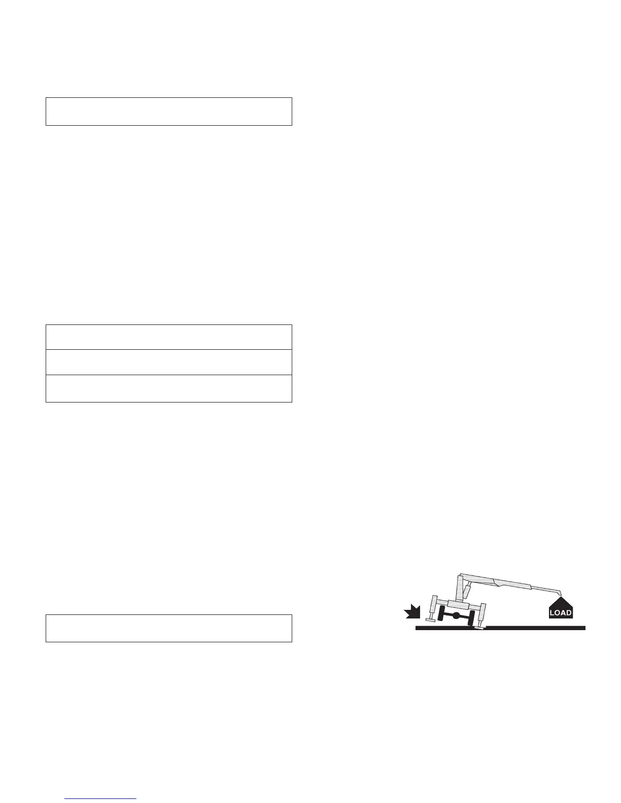
TIPPING
POINT