Selection of Options
‑105‑
Pr = (U × U × D)/(R × K)
The braking resistor power is calculated accordingly.
K is the derating coefficient of the braking resistor. A small value of K prevents the
braking resistor from overheating. K can be increased properly if the heat dissipation
condition is good, but cannot exceed 50%. Otherwise, the braking resistor may be
overheated, which may cause a fire.
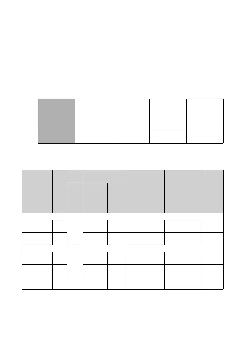
Braking frequency (D) is determined by applications. Typical values of braking
frequency in different applications are listed in "
Table 4–8
"
on page 105
.
Table 4–8 Typical values of braking frequency in different applications
Application General
applications
(such as
translational
conveying)
Vertical lifting Machine tool
spindle
Winding and
unwinding
Braking
Frequency
10% 20% to 30% 30% to 50% 20% to 30%
Braking Unit Models
Table 4–9 Model selection of braking component
Model of Power
Supply Unit
Total
Power
of
Drive
Unit
(kW)
Braking
Unit
125% Braking Torque
(10% ED; Max. 10s)
Minimum Braking
Resistance (Ω)
Maximum Braking
Current (A)
Braking
Power (kW)
Model Recommend
ed Braking
Resistor
Specifica
tions
Number
of
Braking
Resistors
Single‑phase 200–240 V
MD800‑0‑2S24
MD800‑0‑2S24B
2.2 Built‑in
option
al
450 W 66 Ω 1 40 10 2.8
MD800‑0‑2S40
MD800‑0‑2S40B
3.7 740 W 40 Ω 1 20 20 4.7
Three‑phase 380–480 V
MD800‑0‑4T12
MD800‑0‑4T12B
3.7 Built‑in
option
al
740 W 150 Ω 1 55 15 4.7
MD800‑0‑4T22
MD800‑0‑4T22B
7.5 1500 W 75 Ω 1 32 25 9.4
MD800‑0‑4T41
MD800‑0‑4T41B
15 3000 W 38 Ω 1 20 40 18.8

 Loading...


