2-19
Accessory Mounting Dimensions
Product Support: www.instron.com
Accessory Mounting Dimensions
You can attach numerous testing accessories and fixtures to the load frame for specialized
tests. Use the standard mounting holes shown in the following diagrams to mount your
accessories. Avoid tapping new holes that may weaken or otherwise compromise the
integrity of the load frame.
Base Beam
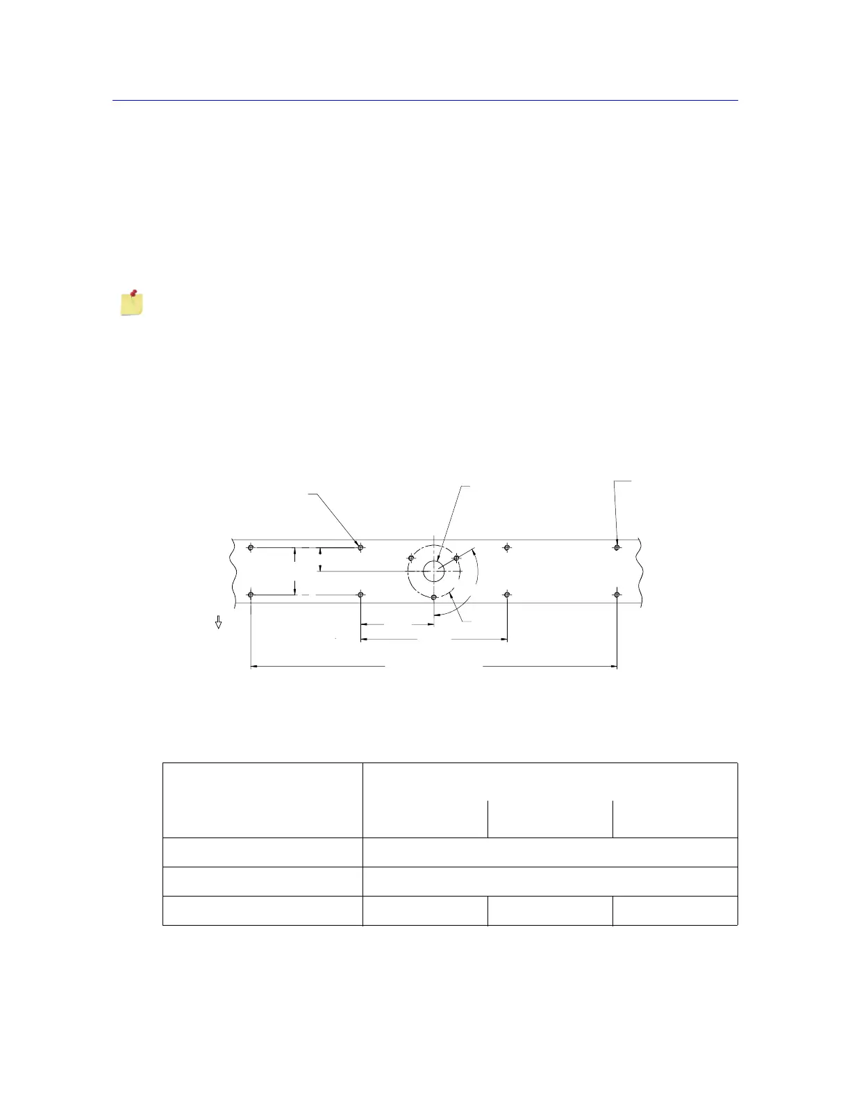
Figure 2-5 on page 2-19 and Table 2-12 on page 2-19 show the accessory mounting
dimensions on the base beam for both standard and extra wide models.
All measurements in the following figures are shown in mm.
Figure 2-5. Base Beam Mounting Dimensions
Ø100
Front of frame
A
C
D
700
140
280
90
45
Table 2-12. Base Beam Mounting Dimensions
Label
Dimension
5965 and 5966 5967 5969
A (7 holes) M10 x 25 deep
C (1 hole) Ø40 x 3 deep
D (4 holes - extra wide only) n/a M10 x 25 deep n/a