49
Mount fixtures
Product Support: www.instron.com
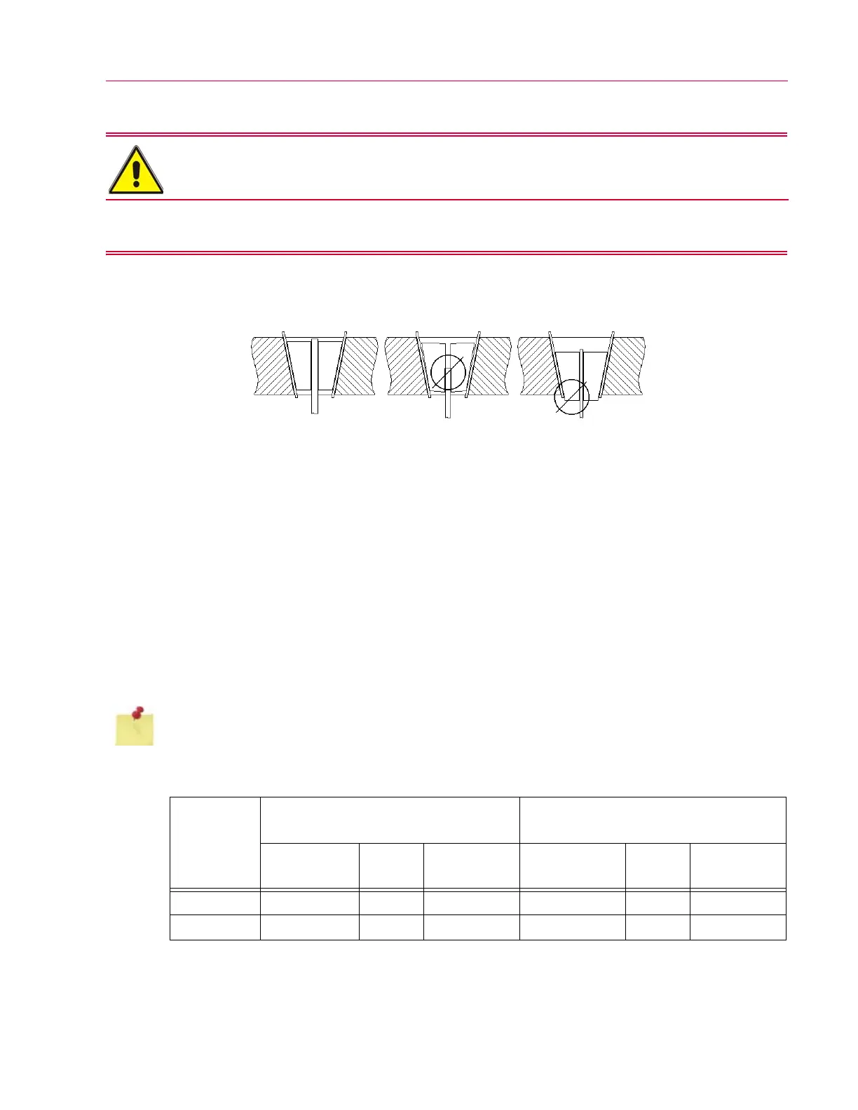
Grip jaws that extend beyond the crosshead during a test will cause serious damage to the
grip jaws and lead to grip pocket deformation. Use as many filler plates as required so that
the narrow end of the grip jaw does not protrude through the crosshead when the specimen
is gripped.
6. Open and close the grip jaws several times using the crank handle to check grip jaw action and
ensure freedom of movement. If the grip jaws stick, remove them and apply more lubricant until the
problem is resolved.
7. Install the grip stop plate on the tension crosshead and secure with the socket head cap screws (use
hex key stated in Table 11).
8. Repeat steps 3 through 6 to install the remaining set of grip jaws into the adjustable crosshead. It is
not necessary to remove the bumper plate from the bottom of the crosshead because the grip jaws
can be inserted into the crosshead through the top of the grip pocket. When step 4 is reached, the
grip jaws must be inserted one at a time into the pocket. Also, remember that the grip jaws must be
inserted with the narrow end up.
9. The grip jaws are now ready to clamp a test specimen. See “Insert specimen” on page 56 for
recommended procedures on inserting a specimen into the grip jaws. When performing repeated
tests with the same set of grip jaws, it will be necessary to apply fresh lubricant to the grip jaws and
filler plates as described in “Lubricate the grip assemblies” on page 72.
Be careful not to injure fingers when inserting heavy filler plates.
Filler plates can be inserted or removed from the tension crosshead with the grip stop plate in place.
Table 11. Specifications for grip stop plate and jaw retainer cap screws.
Frame Model
Grip Stop Plate SHCS
(item 6, Figure 10)
Jaw Retainer BHCS
(item 8, Figure 10)
Size Quantity
Size of Hex Key
Needed Size Quantity
Size of Hex Key
Needed
300DX-G1 M10 x 30 mm 2 8 mm 3/8-16 x 0.75 in 4 7/32 in
600DX-G1 M16 x 35 mm 2 14 mm 3/8-16 x 0.75 in 4 7/32 in