8
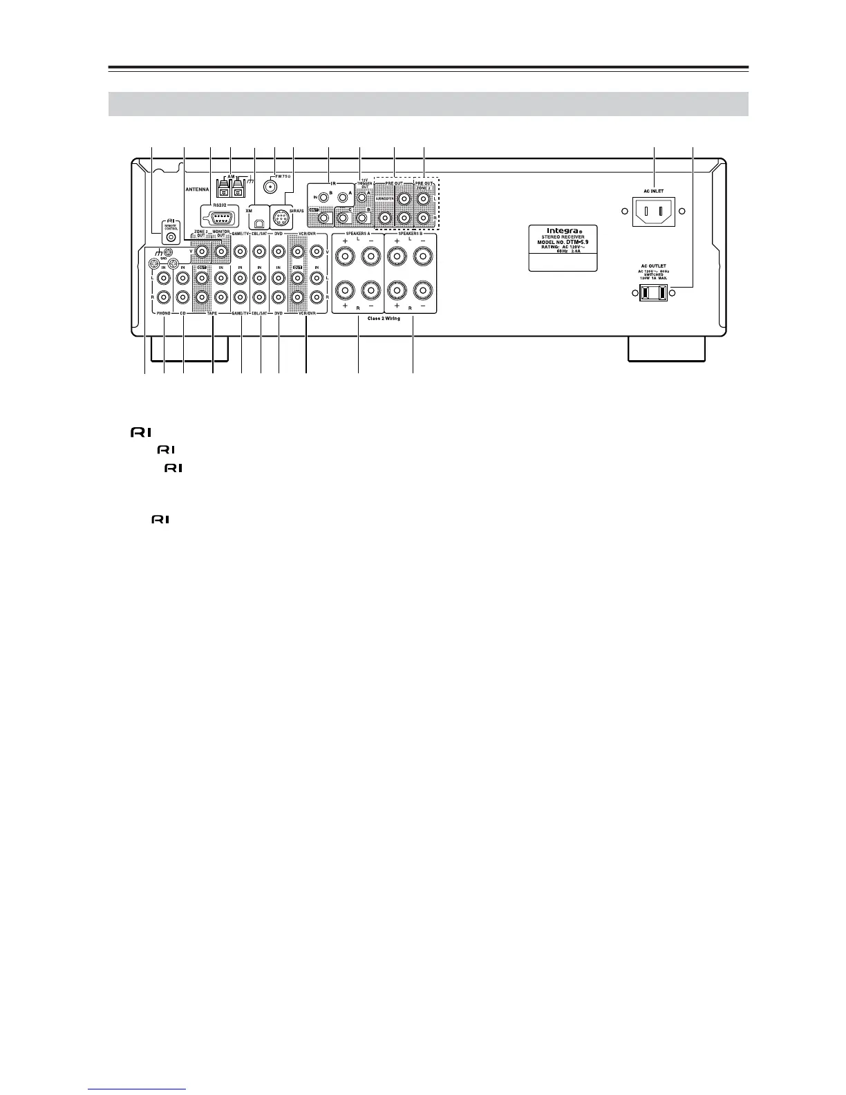
Getting to Know the Receiver—Continued
A REMOTE CONTROL jack
This (Remote Interactive) jack can be connected
to the jacks on your other Integra/Onkyo audio
components. The receiver’s remote controller can
then be used to control all of your components. To
use , you must make an analog audio connection
between the receiver and each component.
B MONITOR OUT
This jack is for connecting a TV with a composite
video output.
C RS232
This port is for connecting the receiver to home
automation equipment and external controllers.
D AM ANTENNA
These push terminals are for connecting an AM
antenna.
E XM antenna
This jack is for connecting a satellite radio such as
the XM Mini-Tuner System, sold separately.
F FM ANTENNA
This jack is for connecting an FM antenna.
G SIRIUS antenna
This jack is for connecting a SIRIUS digital
antenna, sold separately (see the separate SIRIUS
instructions).
H IR IN A/B and OUT
A commercially available IR receiver can be
connected to the IR IN A or B jack, allowing you to
control the receiver while you’re in Zone 2, or
control it when it’s out of sight, for example,
installed in a cabinet.
A commercially available IR emitter can be
connected to the IR OUT jack to pass IR (infrared)
remote control signals along to other components.
I 12V TRIGGER OUT (A/B/C)
These outputs can be connected to the 12-volt
trigger inputs on other components.
J PRE OUT: L/R, SUBWOOFER
This analog audio output can be connected to the
analog audio input on a power amplifier when you
want to use the receiver solely as a preamplifier. The
SUBWOOFER jack is for connecting a powered
subwoofer.
K Zone 2 PRE OUT L/R
These analog audio outputs can be connected to the
line inputs on amplifiers in Zone 2.
L AC INLET
The supplied power cord is connected here. The
other end of the power cord should be connected to
a suitable wall outlet.
M AC OUTLET
This switched AC outlet can be used to supply
power to another component. The type of outlet
depends on the country in which you purchased
your receiver.
N Zone 2 VIDEO OUT
This video output is for connecting video input in
Zone 2.
O PHONO (MM) input and grounding terminal
This analog audio input is for connecting a turntable
with a moving-magnet cartridge. The screw located
on the upper-left of the PHONO (MM) inputs is for
connecting a turntable’s ground wire.
P CD input
This analog audio input is for connecting a CD
player’s analog audio output.
Rear Panel
NOP Q R ST U V W
1 4 6 9 J K L M
B
5
378