14
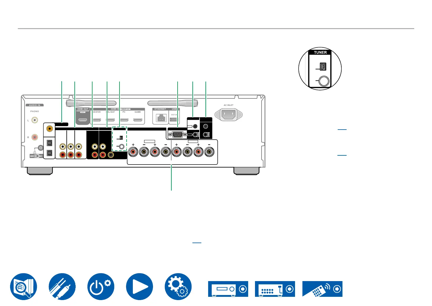
Rear Panel
SPEAKERS
R L
A
L
R
B
FM
75Ω
HDMI OUT HDMI IN ETHERNET USB
HDCP 2.3
BD/DVD CBL/SAT PC GAME
ARC
5V/1A
AUDIO IN
PHONO
L
R
CD
COAXIAL
GAME
TV/TAPE
OPTICAL
AUDIO IN
CD PC
TV/
TAPE
R
L
R
L
PRE OUT
ZONE 2 MAIN
MM MC
GND
DIGITAL IN
SUB-
WOOFER
AM
R
L
AC INLET
PRE/LINE
OUT
TUNER
RS232
IR
OUT
IN
12V TRIGGER
OUT
A
B
J K OL M N P Q
R
J DIGITAL IN OPTICAL/COAXIAL jacks: Input
TV or AV component digital audio signals with a
digital optical cable or digital coaxial cable.
K AUDIO IN jacks: Input AV component audio
signals with an analog audio cable.
*For models that do not have a tuner, the “PC”
jack is changed to a “TUNER” jack.
L ZONE 2 PRE/LINE OUT jacks: Output audio
signals with an analog audio cable connected
(ZONE 2).
M MAIN PRE OUT jacks: Connect a power
→p22)
SUBWOOFER PRE OUT jacks: Connect a
powered subwoofer with a subwoofer cable.
N TUNER AM/FM terminal (*North American
models only): Connect the supplied antennas.
T
B
-
OOFER
TUNER
AM
FM
75Ω
AM
FM
75Ω
O RS232 port: Connect a home control system
equipped with an RS-232C port. For installing
a home control system, contact the specialized
stores.
P IR IN, IR OUT jacks: Connect a remote control
receiver unit. ( →p31)
Q 12V TRIGGER OUT A/B jacks: Connect a
device equipped with a 12V trigger input jack to
enable power link operation between the device
and this unit. ( →p32)
R SPEAKERS terminals: Connect speakers with
speaker cables. (North American models are
banana plug ready. Use plugs with a diameter of
4 mm.)
Connection with spade lugs is not supported.