1000BASE-T/100BASE-TX/10BASE-T Physical Layer Compliance Tests Manual
Intel Confidential 145
100Base-TX Test Procedure for the 82544 Chip
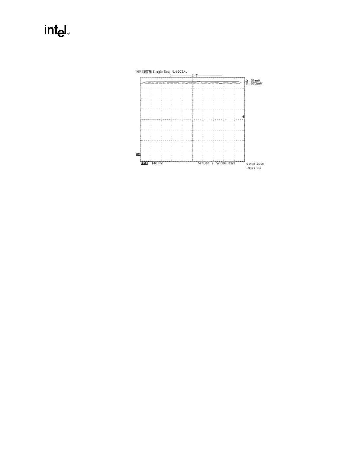
Figure I-10. Positive Pulse Peak, upper cursor
17. Use the data from the last two steps, two calculate the 10% and 90% points for the pulse rise
time and fall time. [See Table I-2 in Section I.4.7.]
18. Select the cross-hair cursors. Move one cursor to 10% of +Vout on the rising edge of the
waveform, and move the other cursor to 90% of +Vout on the rising edge. Rise time is the
difference in time (∆t) between the two markers. To measure the fall time, position the cursors
at 10% and 90% of +Vout on the falling edge of the waveform. Fall time is the difference in
time (∆t) between the two markers. Repeat these measurements on the negative-going
waveform.
Note: Repeat all of these steps for both a positive pulse and for a negative pulse.
For the sake of brevity (and to avoid repetition) example plots are not provided for a negative pulse.
Figure I-11 and Figure I-12 in Section I.4.7 are examples of what the data may look like for a
positive pulse.