resultb = bx * by
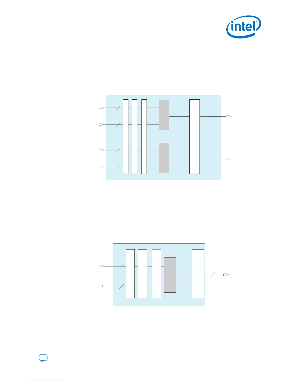
Figure 16. Two 18 × 18 or 18 × 19 Independent Multiplier per Variable Precision DSP
Block
In this figure, the variables are defined as follows:
• n = 19 and m = 37 for 18 × 19 signed operands
• n = 18 and m = 36 for 18 × 18 unsigned operands
resulta[(m-1)..0]
Multiplier
x
Multiplier
x
Input Register Bank
ay [(n-1)..0]
ax [17..0]
n
18
Variable-Precision DSP Block
by [(n-1)..0]
bx [17..0]
n
18
m
resultb[(m-1)..0]
m
Output Register Bank
*1st Pipeline Register
*2nd Pipeline Register
*This block diagram shows the functional representation of the DSP block.
The pipeline registers are embedded within the various circuits of the DSP block.
3.1.1.2. 27 × 27 Independent Multiplier
The 27 x 27 independent multiplier mode uses the equation of resulta = ay * ax.
Figure 17. One 27 × 27 Independent Multiplier Mode per Variable Precision DSP Block
for Intel Agilex Devices
In this mode, the resulta can be up to 64 bits when combined with a chainout adder or accumulator.
Input Register Bank
Multiplier
x
resulta[53..0]
ay[26..0]
ax[26..0]
27
27
54
Variable-Precision DSP Block
Output Register Bank
*1st Pipeline Register
*2nd Pipeline Register
*This block diagram shows the functional representation of the DSP block.
The pipeline registers are embedded within the various circuits of the DSP block.
3. Intel Agilex Variable Precision DSP Blocks Operational Modes
UG-20213 | 2019.04.02
Send Feedback
Intel
®
Agilex
™
Variable Precision DSP Blocks User Guide
33