Figure 19. One Sum of Two 18 x 18 or 18 × 19 Multipliers with One Variable Precision
DSP Block for Intel Agilex Devices
In this figure, the variable is defined as follows:
• n = 19 for 18 × 19 signed operands
• n = 18 for 18 × 18 unsigned operands
Input Register Bank
resulta[37..0]
ay[(n-1)..0]
ax17..0]
n
18
Variable-Precision DSP Block
by[(n-1)..0]
bx[17..0]
n
18
38
Multiplier
Multiplier
Adder
+/-
SUB
Output Register Bank
x
x
*1st Pipeline Register
*2nd Pipeline Register
*This block diagram shows the functional representation of the DSP block.
The pipeline registers are embedded within the various circuits of the DSP block.
Set the SUB dynamic control signal to high to calculate the difference of the two
18 × 19 multiplications.
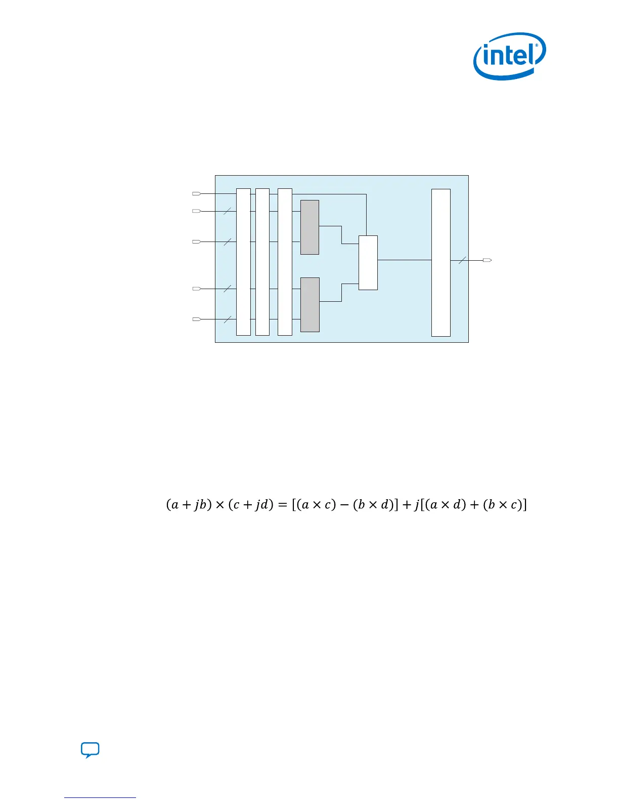
3.1.4. Independent Complex Multiplier
The Intel Agilex devices support the 18 × 19 complex multiplier mode using two fixed-
point arithmetic multiplier adder sum mode.
Figure 20. Sample of Complex Multiplication Equation
The imaginary part [(a × d) + (b × c)] is implemented in the first variable-precision
DSP block, while the real part [(a × c) - (b × d)] is implemented in the second
variable-precision DSP block.
3. Intel Agilex Variable Precision DSP Blocks Operational Modes
UG-20213 | 2019.04.02
Send Feedback
Intel
®
Agilex
™
Variable Precision DSP Blocks User Guide
35