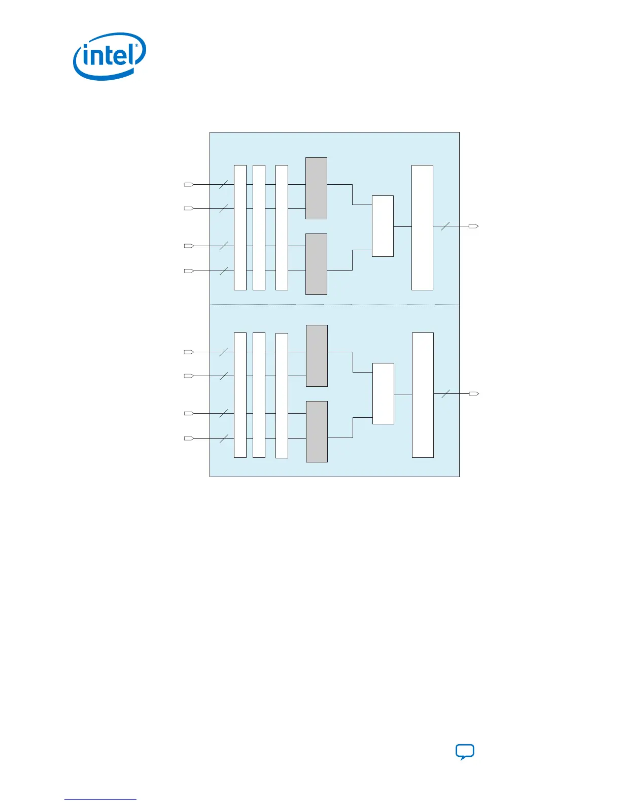
Figure 21. One 18 × 19 Complex Multiplier with Two Variable Precision DSP Blocks for
Intel Agilex Devices
Variable-Precision DSP Block 1
Variable-Precision DSP Block 2
Input Register Bank
Imaginary Part
(ad+bc)
Multiplier
c[18..0]
b[17..0]
19
18
Multiplier
d[18..0]
a[17..0]
19
18
38
Adder
+
x
x
Output Register Bank
Input Register Bank
Real Part
(ac-bd)
d[18..0]
b[17..0]
19
18
c[18..0]
a[17..0]
19
18
38
Output Register Bank
Multiplier
Multiplier
Adder
-
x
x
*1st Pipeline Register*1st Pipeline Register
* 2nd Pipeline Register* 2nd Pipeline Register
*This block diagram shows the functional representation of the DSP block.
The pipeline registers are embedded within the various circuits of the DSP block.
3.1.4.1. 18 × 19 Multiplication Summed with 36-Bit Input Mode
Intel Agilex variable precision DSP blocks support one 18 × 19 multiplication summed
to a 36-bit input.
The 18 × 19 multiplication summed with 36-bit input mode uses the equations:
• resulta = (ax * ay) + bx to sum the 18 x 19 multiplication with 36-bit input.
• resulta = (ax * ay) - bx to subtract the 18 x 19 multiplication with 36-bit input.
Use the upper multiplier to provide the input for an 18 × 19 multiplication, while the
bottom multiplier is bypassed. The bx[35..0] signals the 36-bit input operand.
Use the SUB dynamic control signal to control the adder to perform addition or
subtraction operation.
3. Intel Agilex Variable Precision DSP Blocks Operational Modes
UG-20213 | 2019.04.02
Intel
®
Agilex
™
Variable Precision DSP Blocks User Guide
Send Feedback
36