Figure 22. One 18 x 19 Multiplication Summed with 36-Bit Input Mode for Intel Agilex
Devices
In this figure, the variable is defined as follows:
• n = 19 for 18 × 19 signed operands
• n = 18 for 18 × 18 unsigned operands
Input Register Bank
resulta[63..0]
ay [(n-1)..0]
ax [17..0]
n
18
Variable-Precision DSP Block
bx [35..0]
36
64
Multiplier
Adder
SUB
Output Register Bank
x
+/-
*1st Pipeline Register
*2nd Pipeline Register
*This block diagram shows the functional representation of the DSP block.
The pipeline registers are embedded within the various circuits of the DSP block.
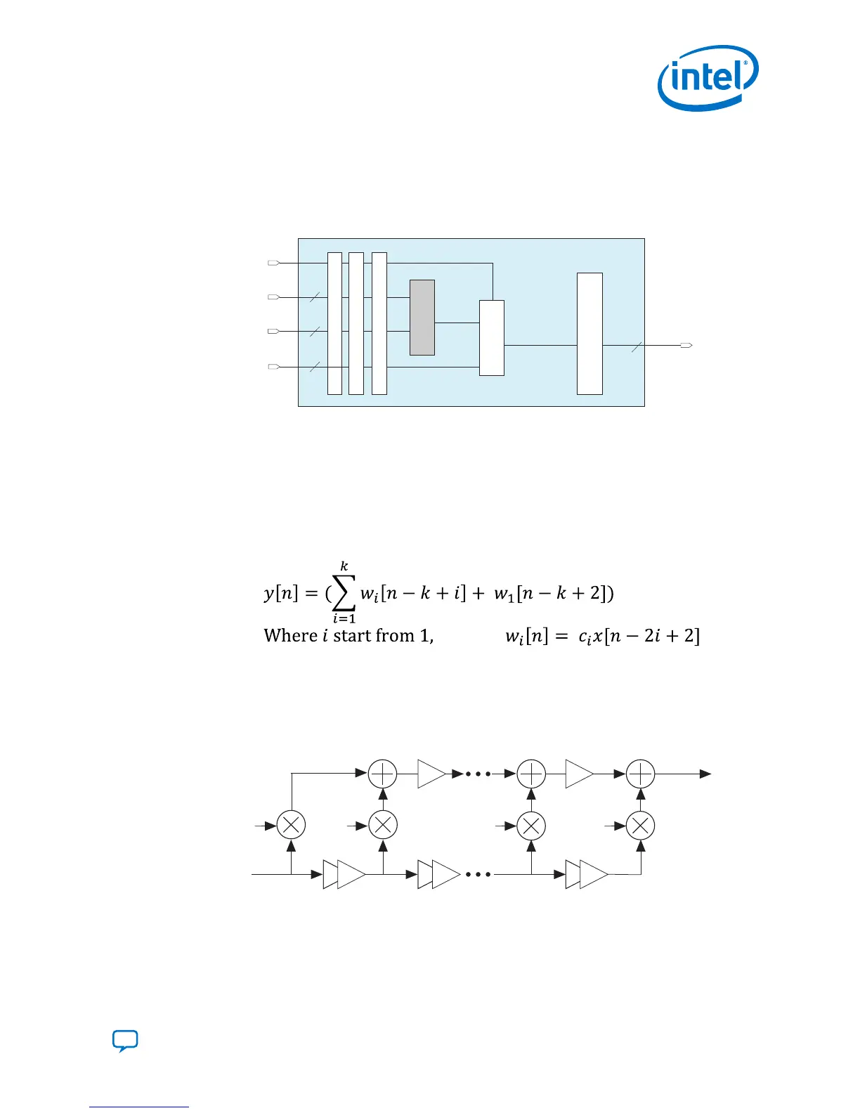
3.1.5. Systolic FIR Mode
The basic structure of a FIR filter consists of a series of multiplications followed by an
addition.
Figure 23. Basic FIR Filter Equation
Depending on the number of taps and the input sizes, the delay through chaining a
high number of adders can become quite large. To overcome the delay performance
issue, the systolic form is used with additional delay elements placed per tap to
increase the performance at the cost of increased latency.
Figure 24. Systolic FIR Filter Equivalent Circuit
Intel Agilex variable precision DSP blocks support the following systolic FIR structures:
• 18-bit
• 27-bit
3. Intel Agilex Variable Precision DSP Blocks Operational Modes
UG-20213 | 2019.04.02
Send Feedback
Intel
®
Agilex
™
Variable Precision DSP Blocks User Guide
37