Electrical
Design Guide 15
3.2 DC Output - Required
3.2.1 DC Voltage Regulation – Required
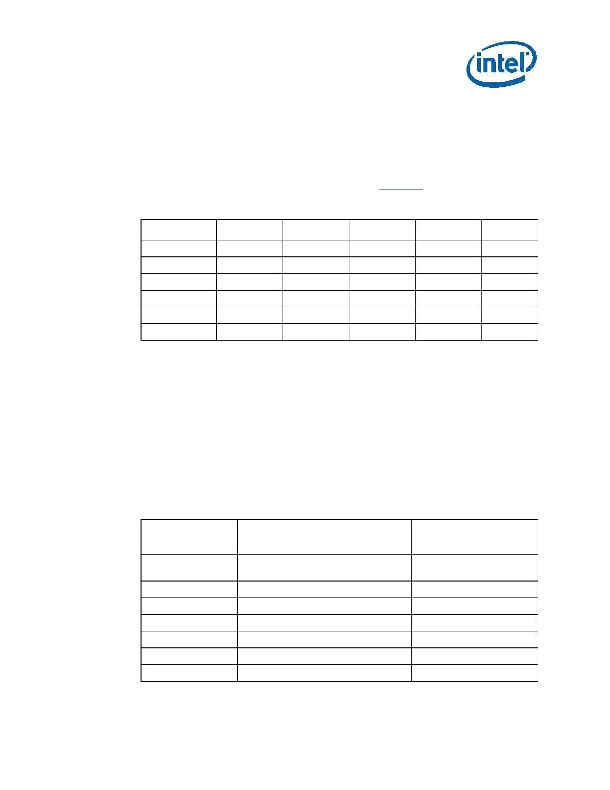
The DC output voltages are required to remain within the regulation ranges shown in
the below table, when measured at the load end of the output connectors under all
line, load, and environmental conditions specified in Chapter 6
.
Table 3-2: DC Output Voltage Regulation
Output Range Min Nom Max Unit
+12V1DC
1
±5% +11.40 +12.00 +12.60 V
+12V2DC
2
±5% +11.40 +12.00 +12.60 V
+5VDC ±5% +4.75 +5.00 +5.25 V
+3.3VDC
3
±5% +3.14 +3.30 +3.47 V
-12VDC
4
±10% -10.80 -12.00 -13.20 V
+5VSB ±5% +4.75 +5.00 +5.25 V
NOTES:
1. At +12V1DC peak loading, regulation at the +12V1DC and +12V2DC outputs can go to
±5%.
2. At +12V2DC peak loading, regulation at the +12V1DC and +12V2DC outputs can go to
±5%.
3. Voltage tolerance is required at main connector and SATA connector (if used).
4. -12VDC output is optional.
3.2.2 DC Output Current – Required
The below table summarizes the expected output transient step sizes for each output.
The transient load slew rate is = 1.0 A/μs. All items in the table below are REQUIRED,
unless specifically called out as RECOMMENDED.
Table 3-3: DC Output Transient Step Sizes
Output
Maximum Step Size
(% of Rated Output Amps)
Maximum Step Size (A)
+12V1DC
40% (Required)
70% (Recommended)
-
+12V2DC 85% -
+12V3/4 80% (Recommended)
+5VDC 30% -
+3.3VDC 30% -
-12VDC - 0.1
+5VSB - 0.5
NOTES: